Archives: Actuator

MLCC ceramic capacitor DC bias derating

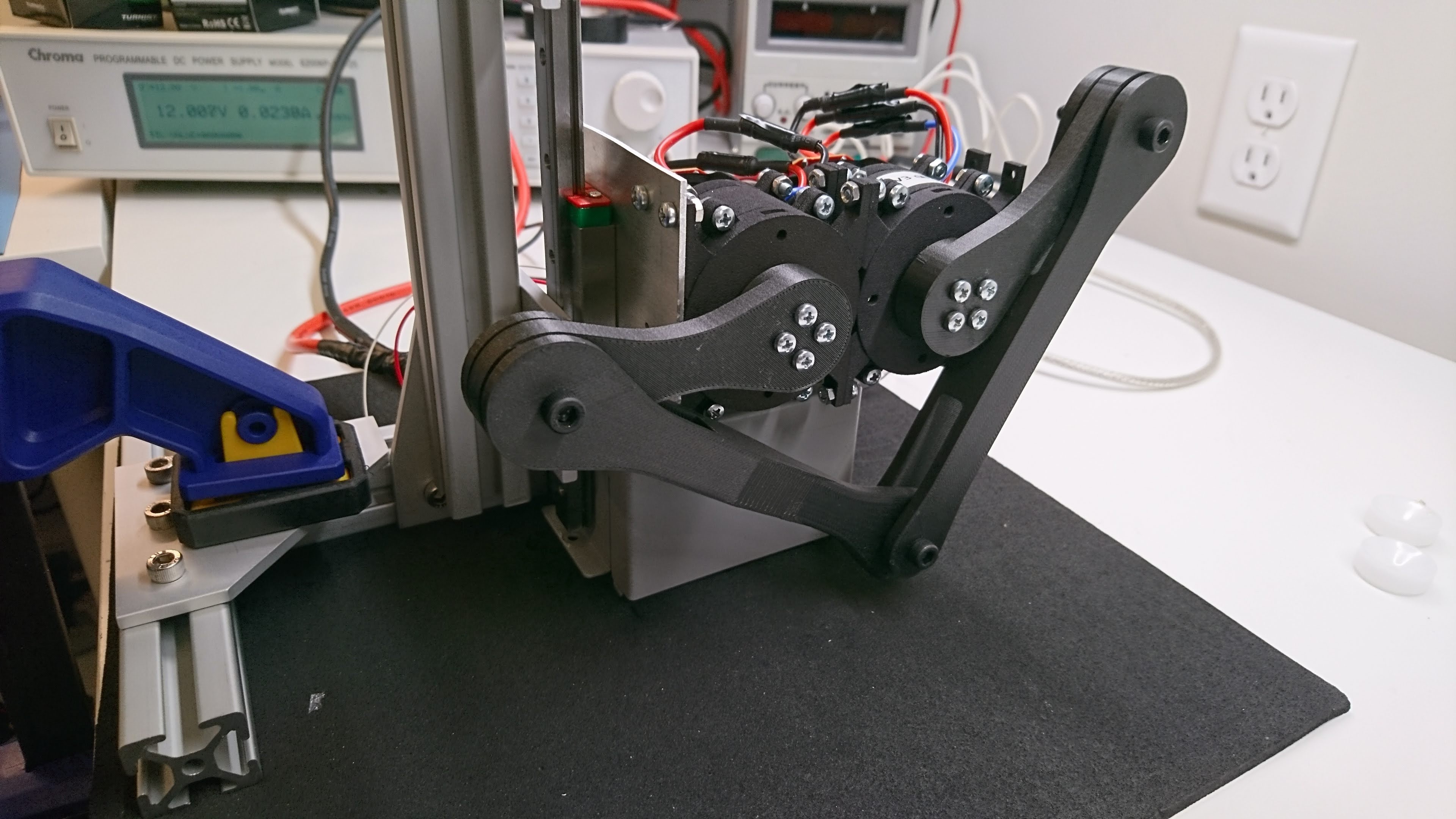
While testing SMMBs new actuator under load, I kept getting faults from overvoltage that I had not anticipated.  The firmware only samples voltage once per control cycle, and while that plot did look very interesting, it probably wasn’t representative.  I wired up the scope to be able to sample the voltage and FET control signals during operation and sure enough, the voltage ripple was way higher than I had predicted based on the original design.  Even at only 30A phase current, the voltage ripple on the main power bus was 4.2V.  Note that this was with a nominal operating voltage of only 13V!  I had been trying to operate at 40A, for which it must have only been worse.

Encoder autocalibration

I have been continuing to iterate on the control and mechanical aspects of the improved actuators for SMMB.  While working on an alternate board mounting strategy, I ended up with a magnet that was much much further from the absolute encoder than before.  This resulted in significant errors in the estimated motor phase at various points in the revolution of the absolute encoder.  In the spirit of copying every single thing Ben Katz did in his project, I implemented a piecewise linear encoder calibration technique.

Brushless actuator control board, r2

The first revision of the brushless servo control board for SMMB was successful in getting a leg to jump.  I ended up doing a small-run second revision that addressed a few minor problems and added a couple more capabilities.

  • RS422 Debug/Link Port: I had a 3.3V serial port exposed previously for debugging, however it caused my USB-serial converter to dislike itself due to common mode ground shifts and it wasn’t reliable at high baud rates (>3Mbps).  I also wanted to support “linked” modes, where two servos would perform control in the actuator space at full rate.
  • Debug through holes: r1 had a number of debug connections, all of which were unpopulated SMD pads.  I decided that through holes were easier to connect debug wires to.
  • Vertical SWD connector: I had initially thought I would hide the SWD connector within an enclosure.  However, the initial enclosure prototypes made that seem less desirable, so I switched it to vertical.
  • More debugging points: When bringing up the first board, I ended up doing a lot of carefully balancing scope probes on various pins, when there was plenty of board room to just have through hole debug points.  Lesson learned.
  • FET temperature sensing: r1 just had an external temperature sensor port, r2 additionally has a thermistor next to the FETS.

Macrofab’s current pricing scheme provides a great incentive to keep your BOM below 20 parts, as that is the only way to get quick turn service.  Otherwise you pay an extra 2 or 3 weeks of calendar time.  In r1, I went to some lengths to stay under 20, however, it just wasn’t going to work with r2, so I left a few easy-ish or non-critical parts unpopulated to do them myself: the connectors, LEDs, and one really big diode.

Pinions, set screws, and glue

One of my intermediate goals for building new actuators for SMMB is to get them robust enough to jump continuously for some duration of time.  Progress is slow, as things break, new parts are ordered, repairs are made, and jumping resumes.  The most recent failure is at least interesting enough to me that it is worth writing up.

To recap, I’m building a brushless servo based around a Turnigy Elite 3508 brushless motor and a custom 5x planetary gearbox.  The 3508 is intended for quadcopter applications, so to install a spur gear I first extracted the original shaft, then pressed in a new shaft with two flats on it.  One flat for the set screw attaching the rotor to the shaft (which had a press fit), and a second for the set screw attaching the spur gear to the output of the shaft.

Slow motion leg jump

After the initial leg jumping with the prototype brushless actuator for SMMB, I spent some time actually tuning the control loops and making the firmware not incredibly convoluted to get started.  I also acquired a high speed camera for analysis.

So, here is a brief update of the final jump before I seem to have toasted one of my DRV8323 motor drivers.  It jumped for about 400ms of hang time, running at about half of the maximum current the system should be capable of pulling.

More robust jumping fixture

In my first foray into 80/20, I built a slightly more robust jumping fixture for the SMMB leg jumping test:

DSC_1246

Overall it is much more rigid than the old one, and looks a little nicer.  To top it off, I laid down a neoprene sheet for surface protection and friction enhancement, which is a step up from the old cardboard surface both in aesthetics and function.

First day jumping!

I continue to make progress on the improved actuators for SMMB.  To briefly recap, these are based on a home-built brushless servo consisting of off the shelf gears, bearings, 3d printed assemblies, and a custom control board.

Moving on from closed loop vector (FOC) control, I’ve now built up a second motor, set both of them communicating over the same RS485 bus, and wired up a minimal makeshift jumping fixture.  The leg didn’t jump as well as I had expected: I was only able to achieve about 300ms of air time and there are a lot of other minor problems/deficiencies as well.  But on the other hand, I don’t appear to have permanently broken anything yet, so improvement will hopefully be mostly continuous!

First closed loop vector control

I’ve reached a minor milestone in developing improved actuators for Super Mega Microbot.  Previously I demonstrated basic closed loop control using a VESC.  Now I have a custom control board running closed loop vector-based current and position control on a single brushless servo!  I’ll hopefully write up pieces in more depth later, but this post can serve as a proof of existence.

First, boards as received from MacroFab:

Mounted onto the planetary gearbox:

rules_mbed - bazel for mbed

When working on the firmware for Super Mega Microbot’s improved actuators, I decided to try using mbed-os from ARM for the STM32 libraries instead of the HAL libraries.  I always found that the HAL libraries had a terrible API, and yet they still required that any non-trivial usage of the hardware devolve into register twiddling to be effective.  mbed presents a pretty nice C++ API for the features they do support, which is only a little less capable than HAL, but still makes it trivial to drop down to register twiddling when necessary (and includes all of the HAL by reference).

Shapeways dimensional tolerances

The first version of the planetary gearbox as 3d printed from Shapeways required a fair amount of post-machining to get all the pieces to fit together.  I wanted to get to a point where I could just order some parts and have a reasonable expectation of them mostly working out of the box.  To make that happen, I’d need to get a better understanding of where the tolerances were coming from.

Understanding the problem

Shapeways provides a fair amount of documentation on the processes and accuracy you can expect generally.  Most of this is detailed in “Design rules and detail resolution for SLS 3D printing”, however the results there have some limitations.  Primarily, they are only applicable to the specific geometries tested.  Shrinkage is qualified as +- 0.15% of the largest dimension, and is likely influenced by the exact printed geometry.  Secondarily, in the documented tests, the designers had full control over the part alignment in the print.  The standard shapeways platform does not allow you to orient parts, you are at the whim of their technicians where the Z axis will end up.