Prusa MK3s printed legs
All my testing to date on the improved actuators for SMMB have used 3d printed parts from Shapeways. Both to have a faster iteration time, and to reduce costs, I’ve optimized all the parts to be printed on my Prusa MK3s.
Here’s all of the individual parts:
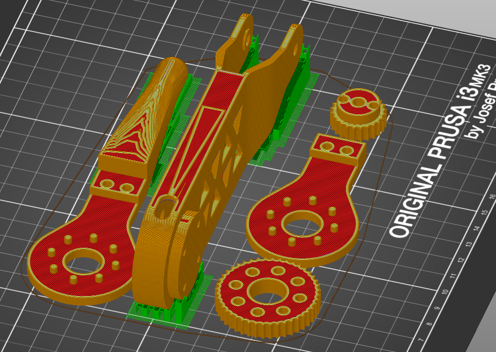
Leg parts laid out in Slic3r Prusa Edition
Them assembled into a leg with the other necessary hardware: