Rotor removal, and complete disassembly
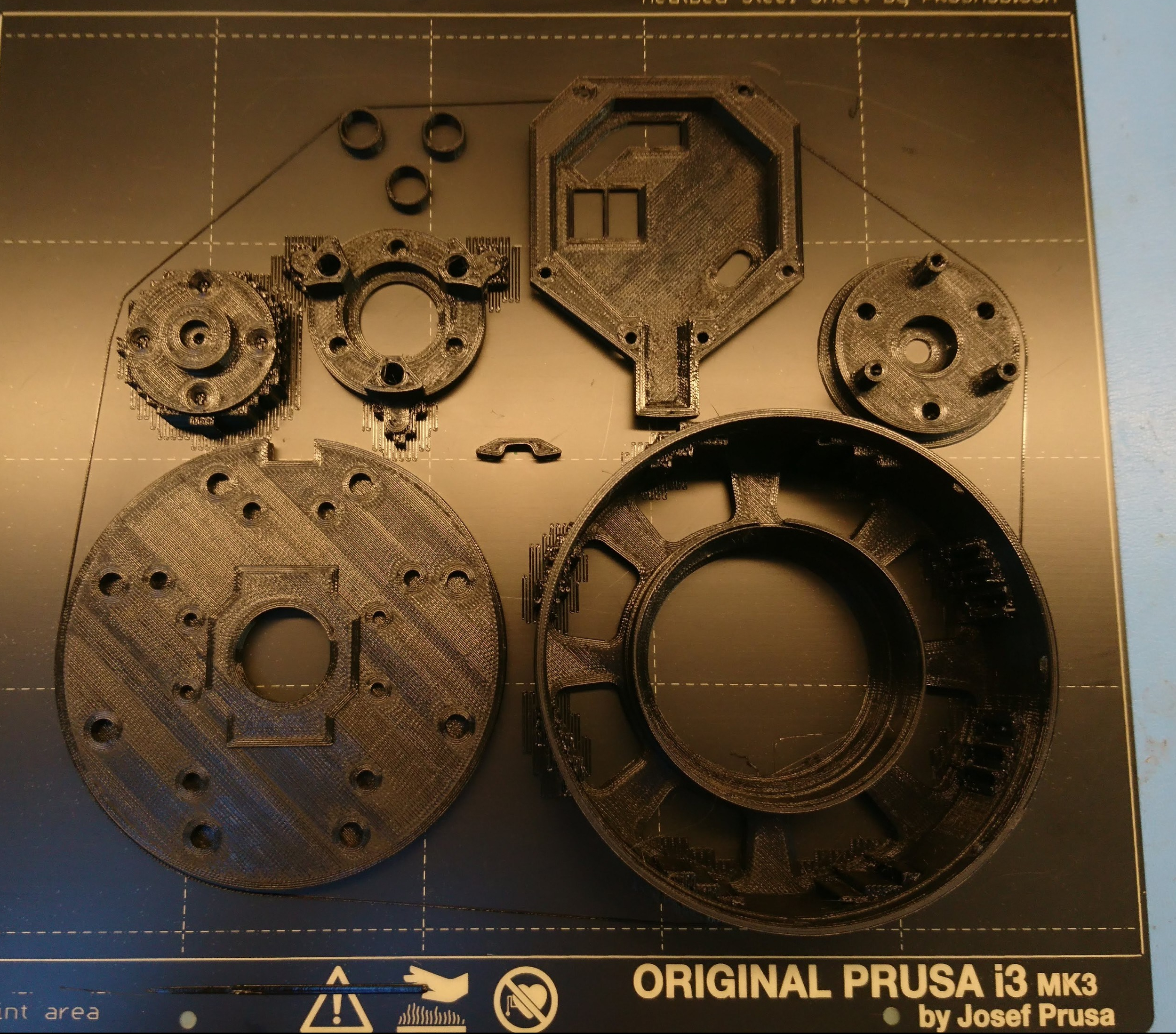
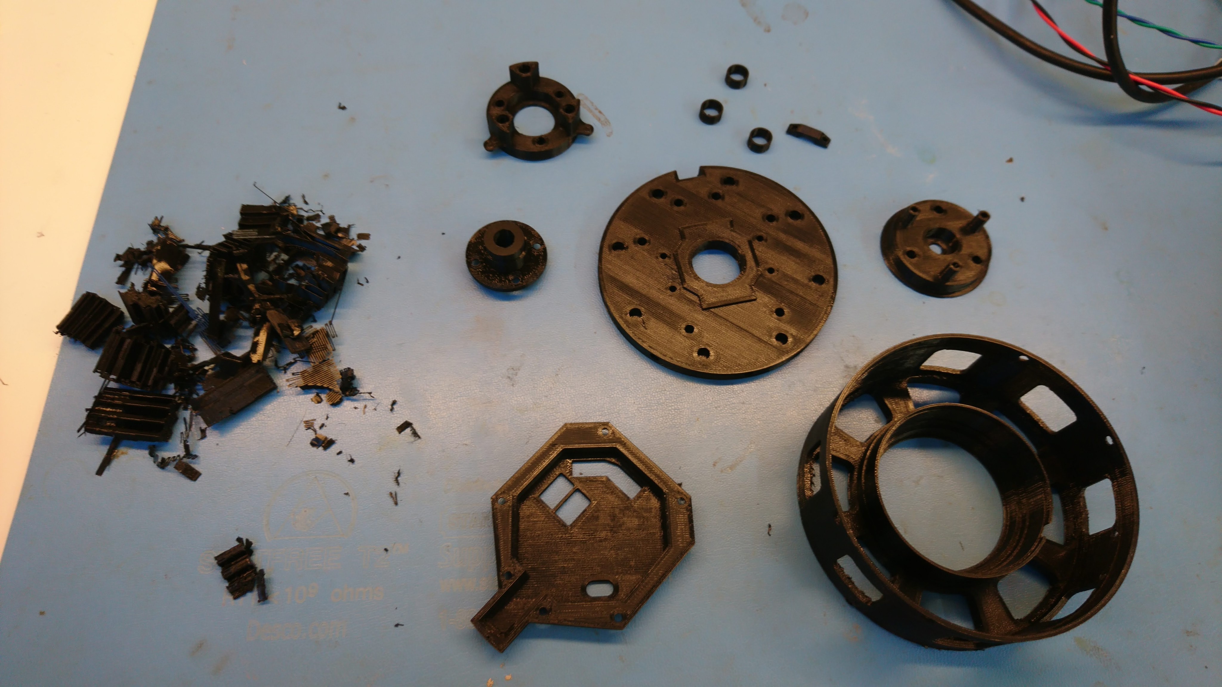
So, last time I had a functioning gear-train, I just needed to disassemble everything in order to replace the outer housing. As I was putting things together, I realized that several custom fixtures would likely be needed in order to disassemble various parts cleanly. Here, I made a giant 3D printed cylinder that the front housing and planet output would bolt to, and then the central shaft could be pressed out.