Archives: Actuator

AS5600 support for moteus auxiliary encoders

The initial implementation of auxiliary encoders for moteus supported exactly one encoder, the AS5048B. The hardware can support any I2C based encoder, so supporting additional encoders has always been on the TODO list.

I’m excited to announce, that as of firmware release 2021-12-03, AS5600 encoders are now supported as well. They are a lot cheaper than the AS5048 as they have a much lower update rate and resolution, but that isn’t necessarily a problem if it is only used to disambiguate a modest gear reduction.

Auxiliary encoders for moteus

The moteus controller uses an absolute magnetic encoder to sense the position of the rotor in order to conduct field oriented control of the motor. In many applications, this sensing is also sufficient to measure the output as well, particularly in direct drive applications. However, if the controller is driving the output through a gear reduction, multiple turns of the input are necessary to make one turn on the output. At power on, this results in an ambiguity, where the controller doesn’t know where the output is.

Dealing with stator magnetic saturation

In my previous experiments demonstrating torque feedback (full rate inverse dynamics, ground truth torque testing), I’ve glossed over the fact that as the stator approaches magnetic saturation, the linear relationship between torque and current breaks down. Now finally I’ll take at least one step towards allowing moteus to accurately work in the torque domain as motors reach saturation.

Background

The stator in a rotor consists of windings wrapped around usually an iron core. The iron in the core consists of lots of little sub-domains of magnetized material, that normally are randomly oriented resulting in a net zero magnetic field. As current is applied to the windings, those domains line up, greatly magnifying the resulting magnetic field. Eventually most of the sub-domains are aligned, at which point you don’t get any more magnifying effect from the iron core. In this region, the stator is said to be “saturated”. You can read about it in much more depth on wikipedia or with even more detail here. The end result is a curve of magnetic field versus applied current that looks something like this:

Testing qdd100 stator windings

My initial design torque for the qdd100 was a little over 17 Nm. However, when I did my first ground truth torque testing, I found that some servos had a lower maximum torque than I had specified. While working to diagnose those, I built a qdd100 that used an alternate stator winding of 105Kv instead of the 135Kv that are in all the beta units. The Kv rating of a stator describes how fast the motor will spin for a given applied voltage. If you assume the same amount of copper mass of wiring, a lower Kv will mean that there are thinner wires that wrap around the stator more turns (or fewer wires in parallel). A higher Kv will have thicker wires with fewer overall turns.

Making the reduced weight servo mk2

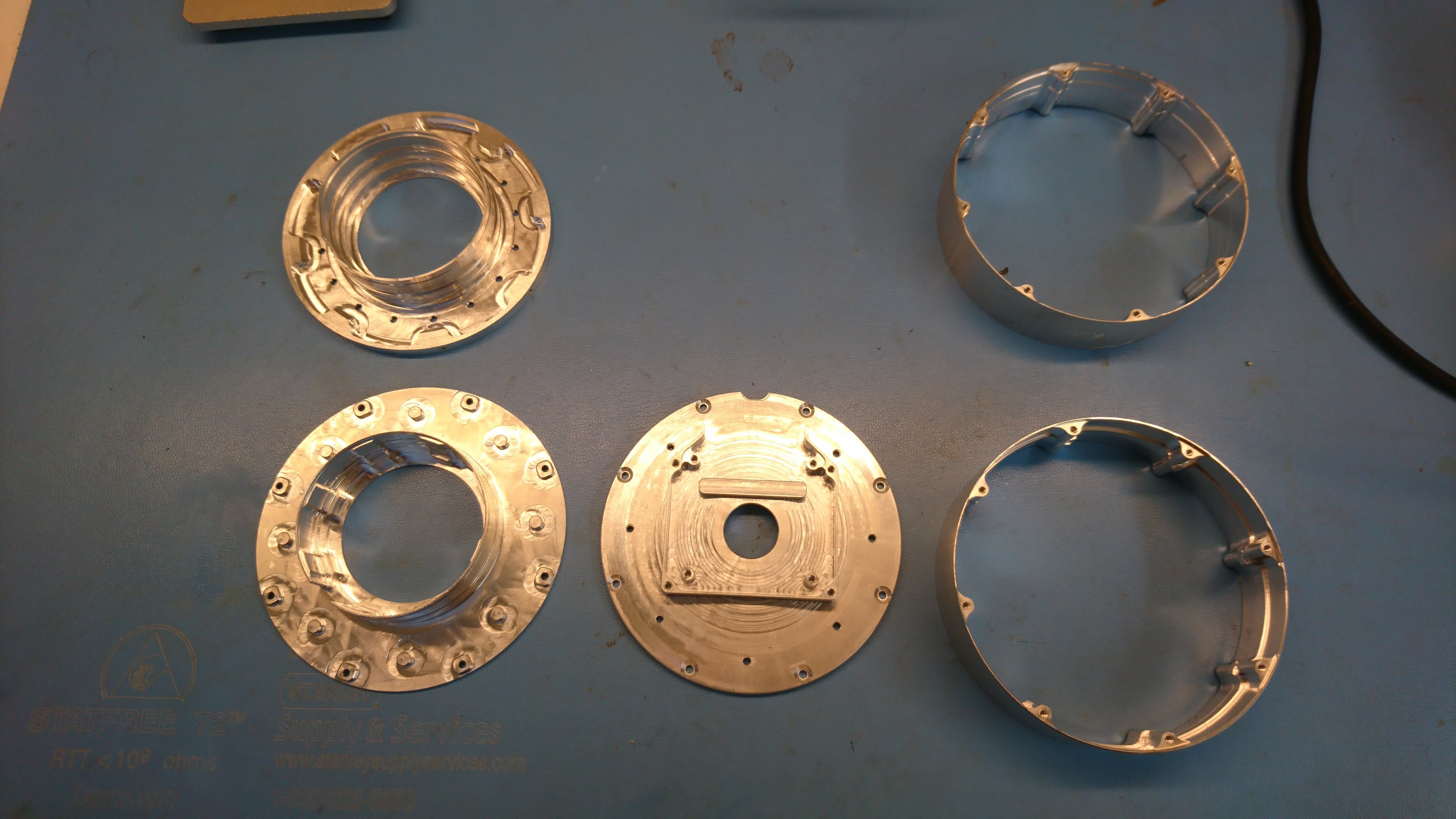
Earlier I described my design plan for reducing the overall mass of the moteus servo mk2.  Constructing a prototype of this turned out to take many more iterations and time than I had expected!  Along the way I produced and scrapped two front housings, two outer housings and a back housing.

Soooo much PocketNC time for naught!

Soooo much PocketNC time for naught!

I made one complete prototype which only had the weight reduction applied to some of the parts and lacked a back cover and any provision for a wire cover.  It was the one from the moteus controller r4.1 juggling video:

First walking with gearbox chassis

Short recap: After building the quadruped with near-direct drive motors, I discovered that the lateral servos had insufficient position control authority to keep the robot standing up.  Thus I embarked on a now month long quest to design and build an integrated planetary gearbox.  At this point, I have enough gearboxes built for all the lateral servos, so it should be able to walk, right?

And tada!  It can!  Well, at least a little bit.  I’ve only spent a short while with the gearbox based chassis, and have a lot of work left to do.  However, here’s a quick video showing it walking around, slipping on a ruler, and almost falling over a few times.

Wiring up the gearbox chassis

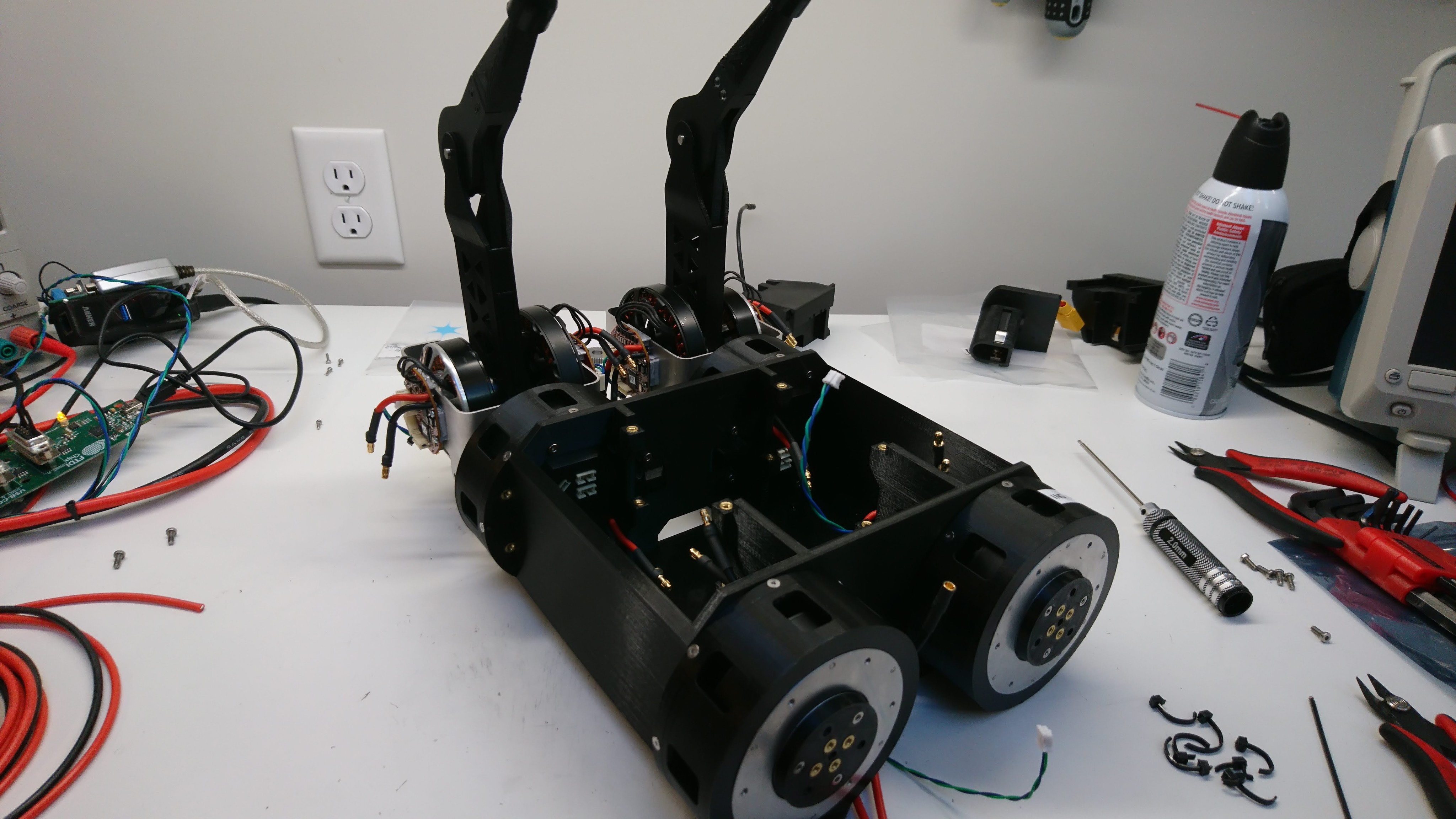
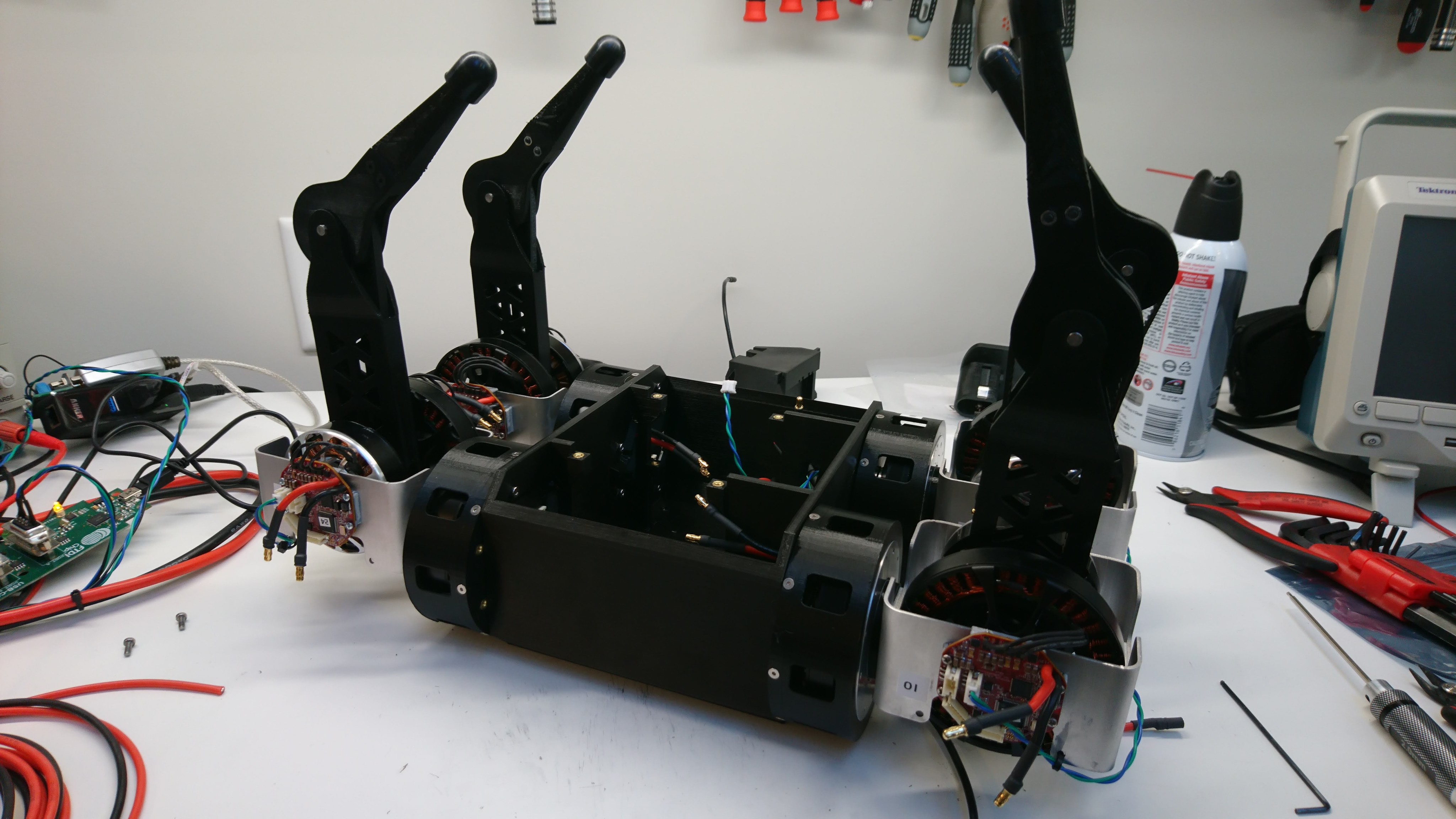
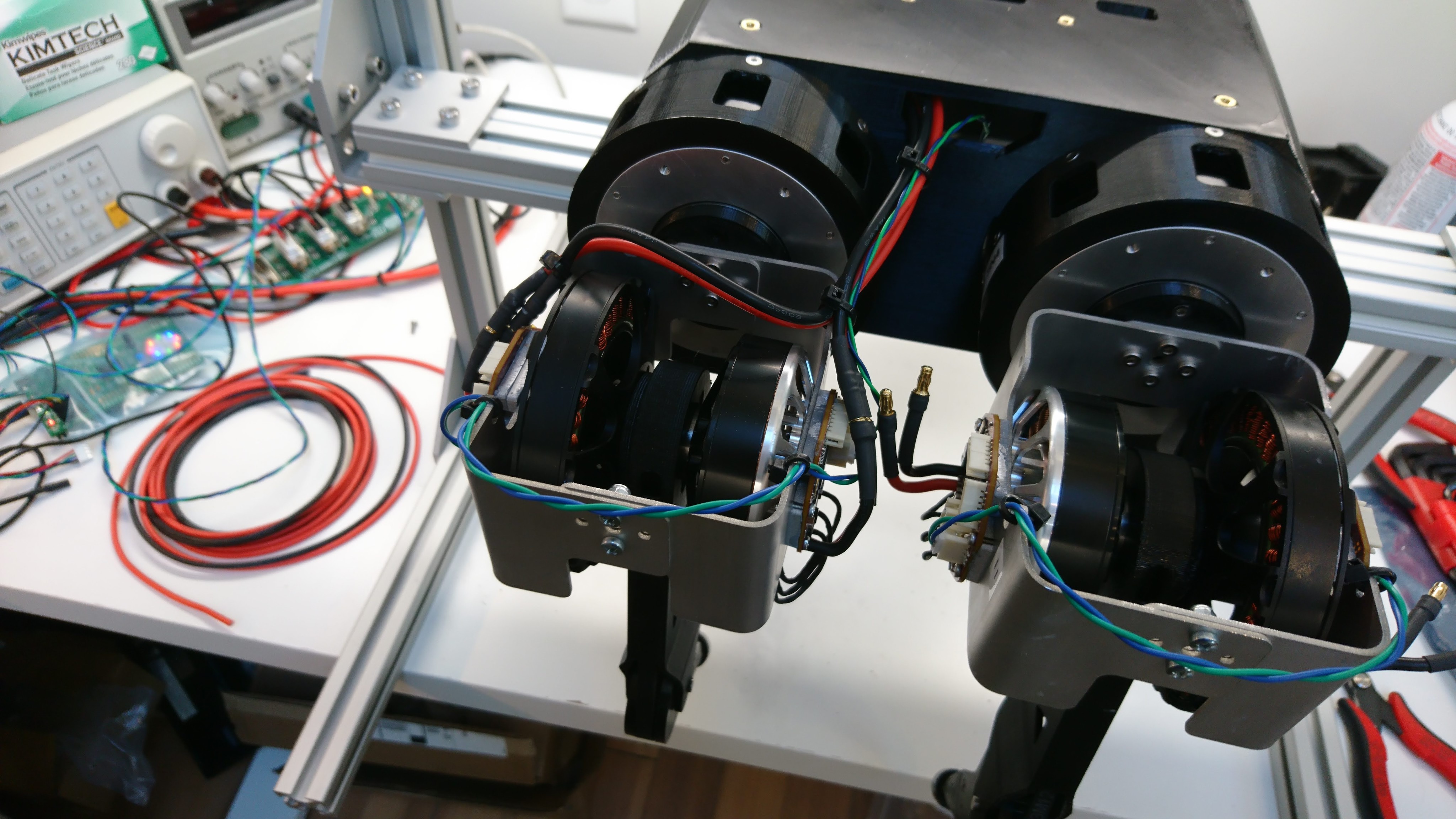
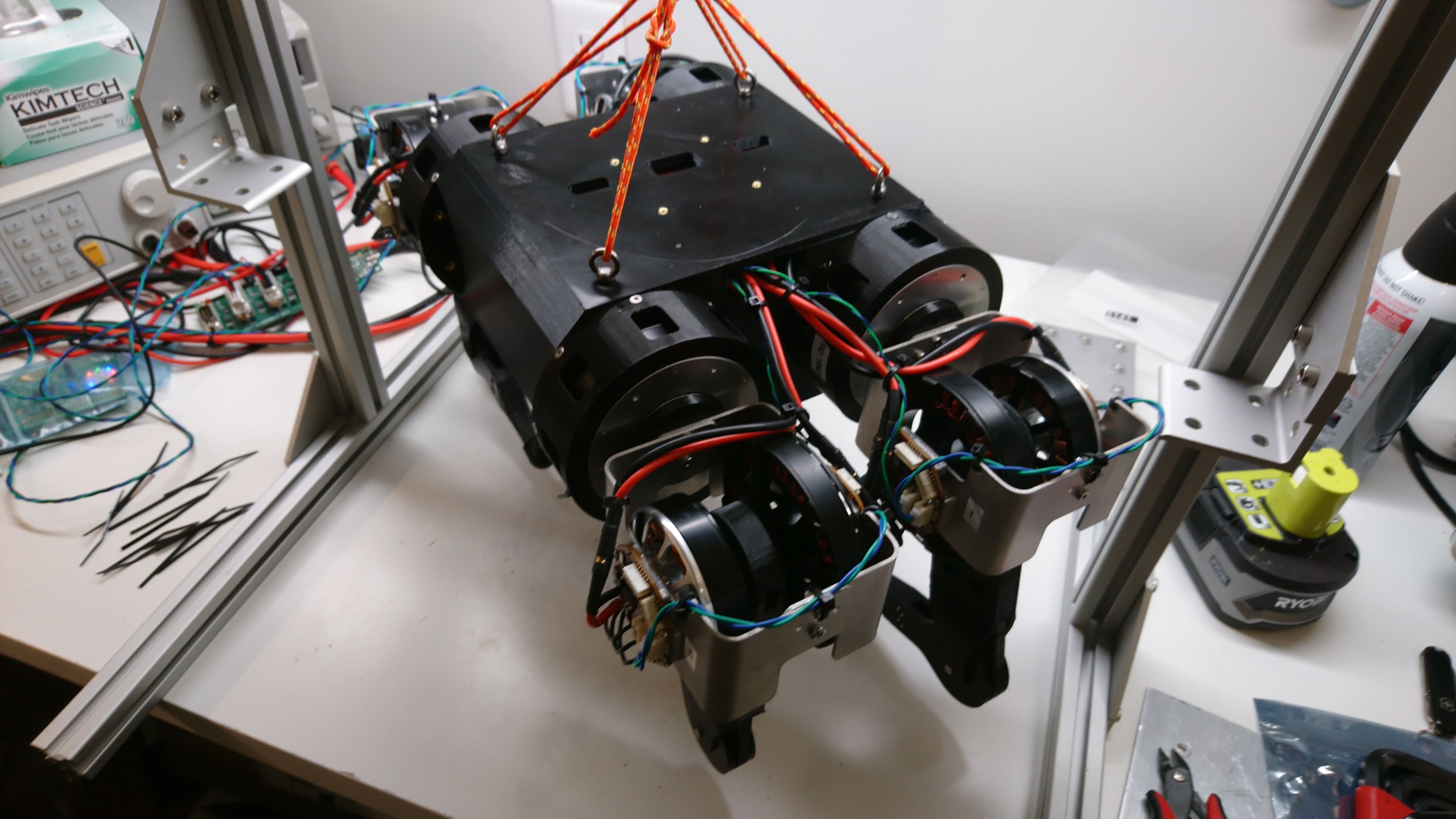
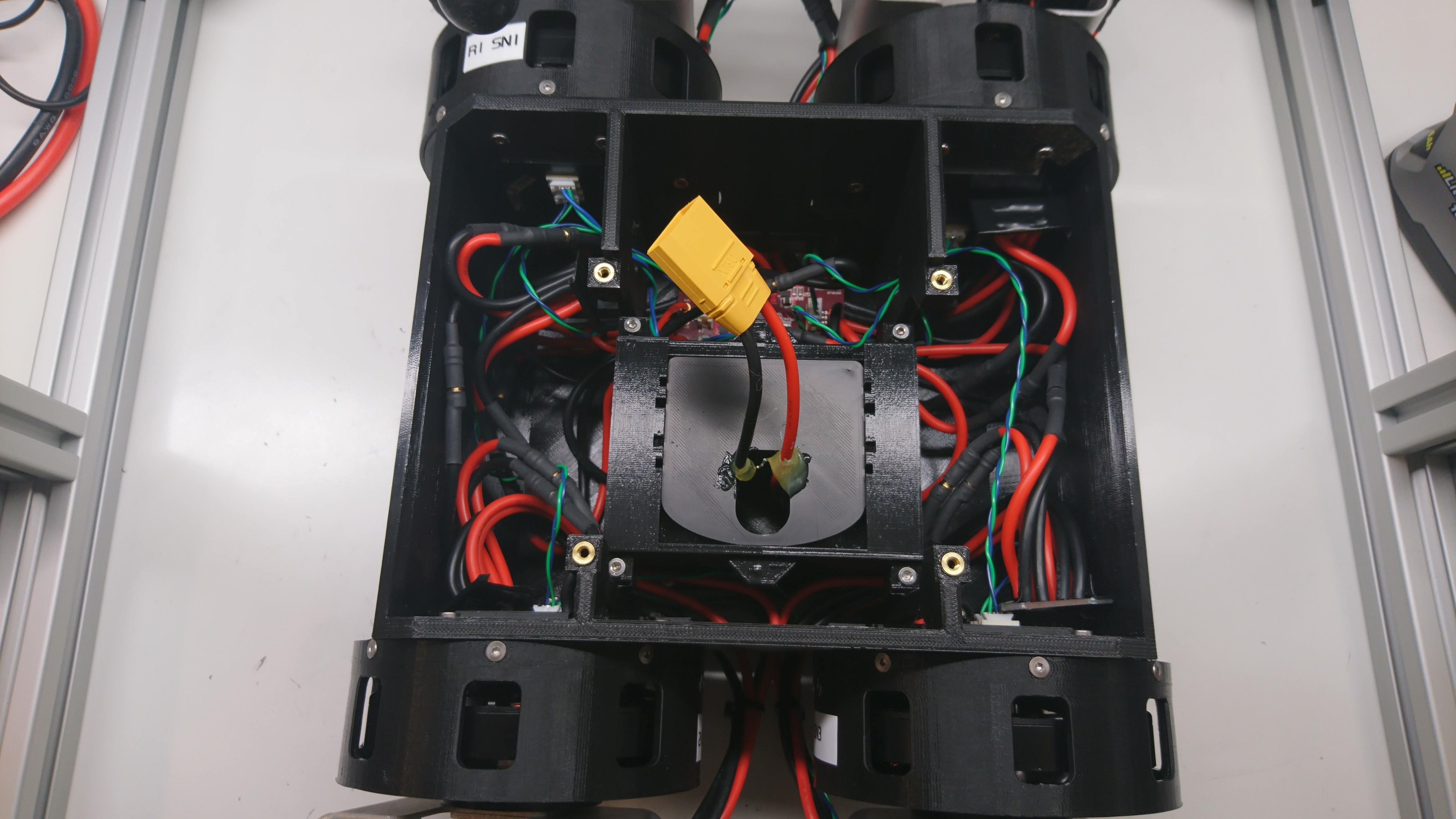
Now that I had a set of 4 at least minimally working lateral servos, I needed to wire up the chassis so that everything had power and data.  Here are some pictures of that process:

Two legs installed

Two legs installed

Four legs installed

Four legs installed

Joint cable routing

Joint cable routing

Times four

Times four

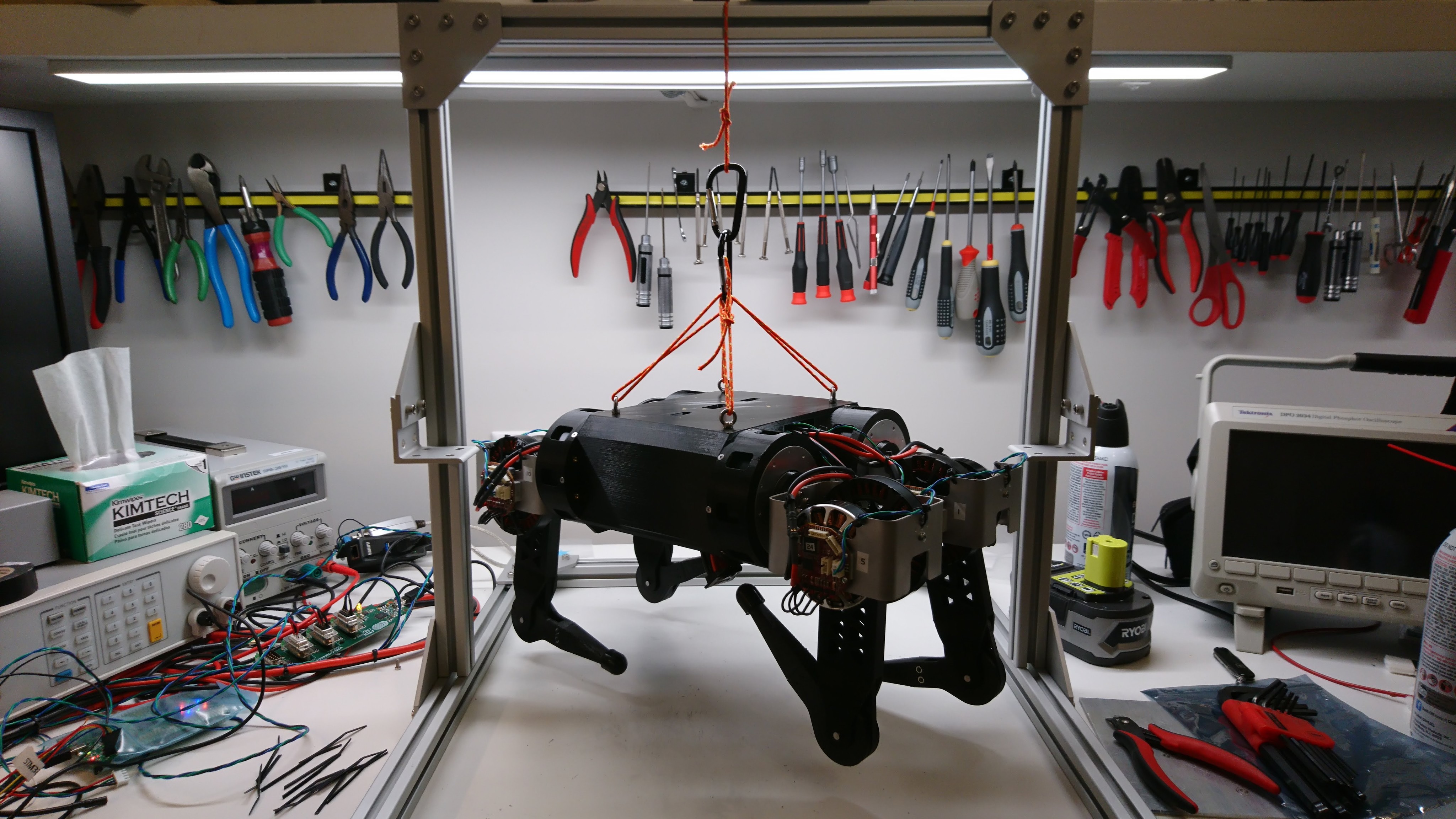
Suspended from the test fixture

Suspended from the test fixture

Four sets of busbars, the junction board, and a shore power battery simulator

Four sets of busbars, the junction board, and a shore power battery simulator

Lateral servo gearbox build(s)

After completing one gearbox, I needed to build at least 4 more of them to replace the lateral servos on Super Mega Microbot (2).  So, I got to work.  First, I disassembled 5 more BE8108 motors.

dsc_2140

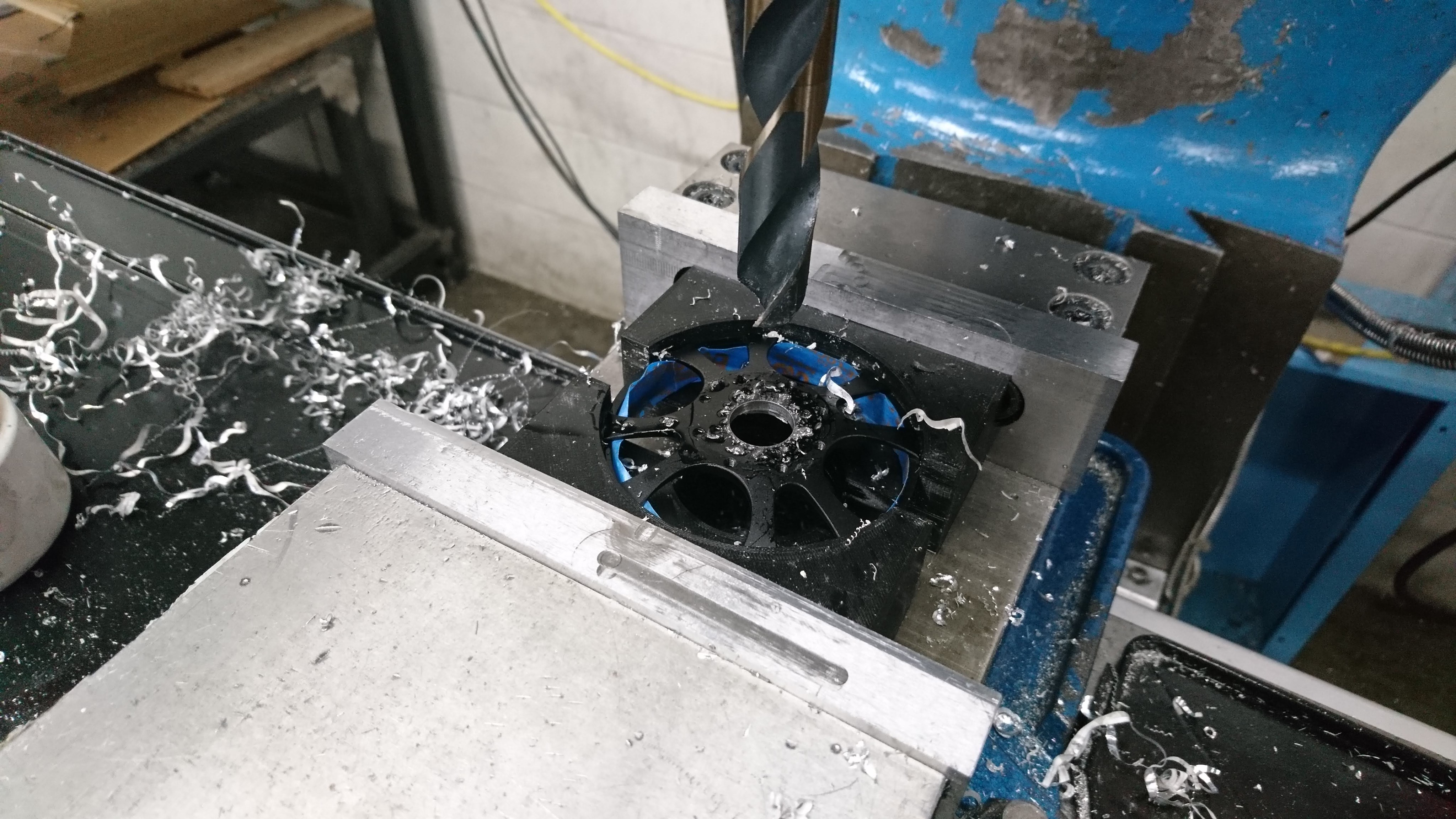
Then, I drilled out the rotors, this time using the mill at AA.

dsc_2145

Next I removed the stators from their backing.  This was painful enough last time, that I tried a new technique using the mill to do most of the work.  Unfortunately, one of the stators was critically damaged during my initial experimentation.  So, now down to 4 survivors.

Rebuild of gearbox assembly

After finally getting the darned thing apart, and printing a new outer housing, I went about re-assembling the whole mechanism.  This time, I tried to take care to make the future disassembly less painful.

To start with, I filed down the problematic outer bearing interfaces of the sun gear holder so that the bearings were a slip fit over them.  These two interfaces don’t need to be particularly snug, so that was easy enough, if monotonous, to accomplish.  I also machined out a some pockets around the magnet hole, to make it possible to just hot-glue the position magnet in place and more easily extract it.