Archives: 3dprint

New Mech Warfare turret

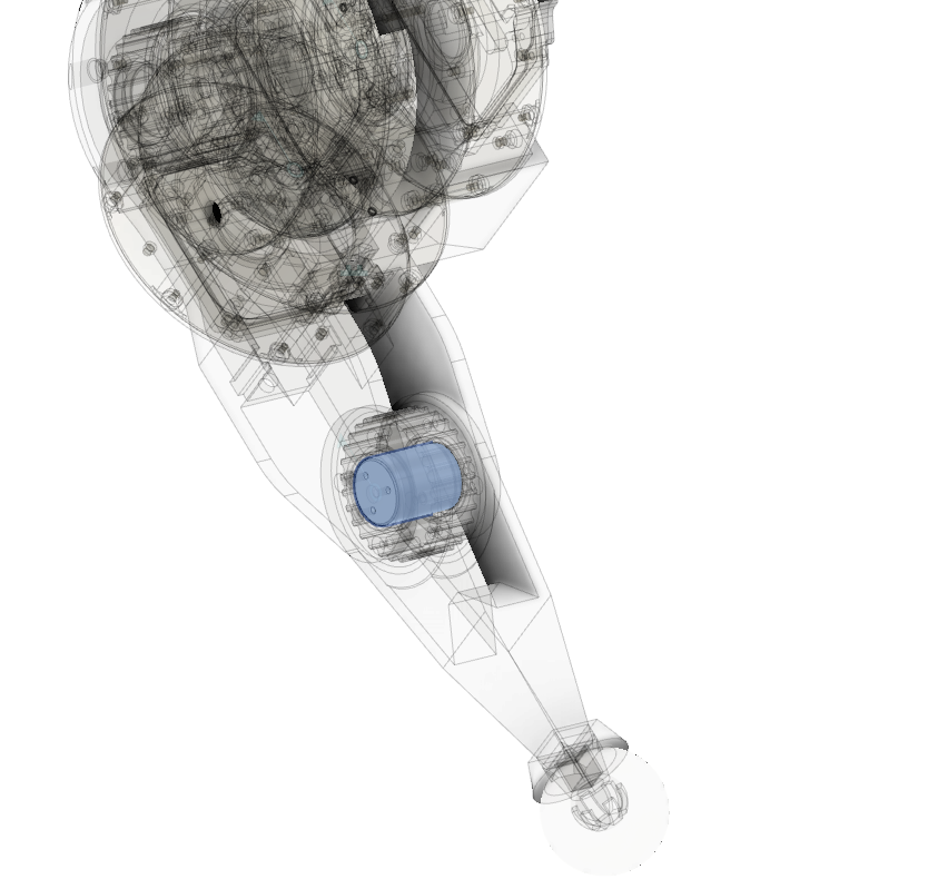
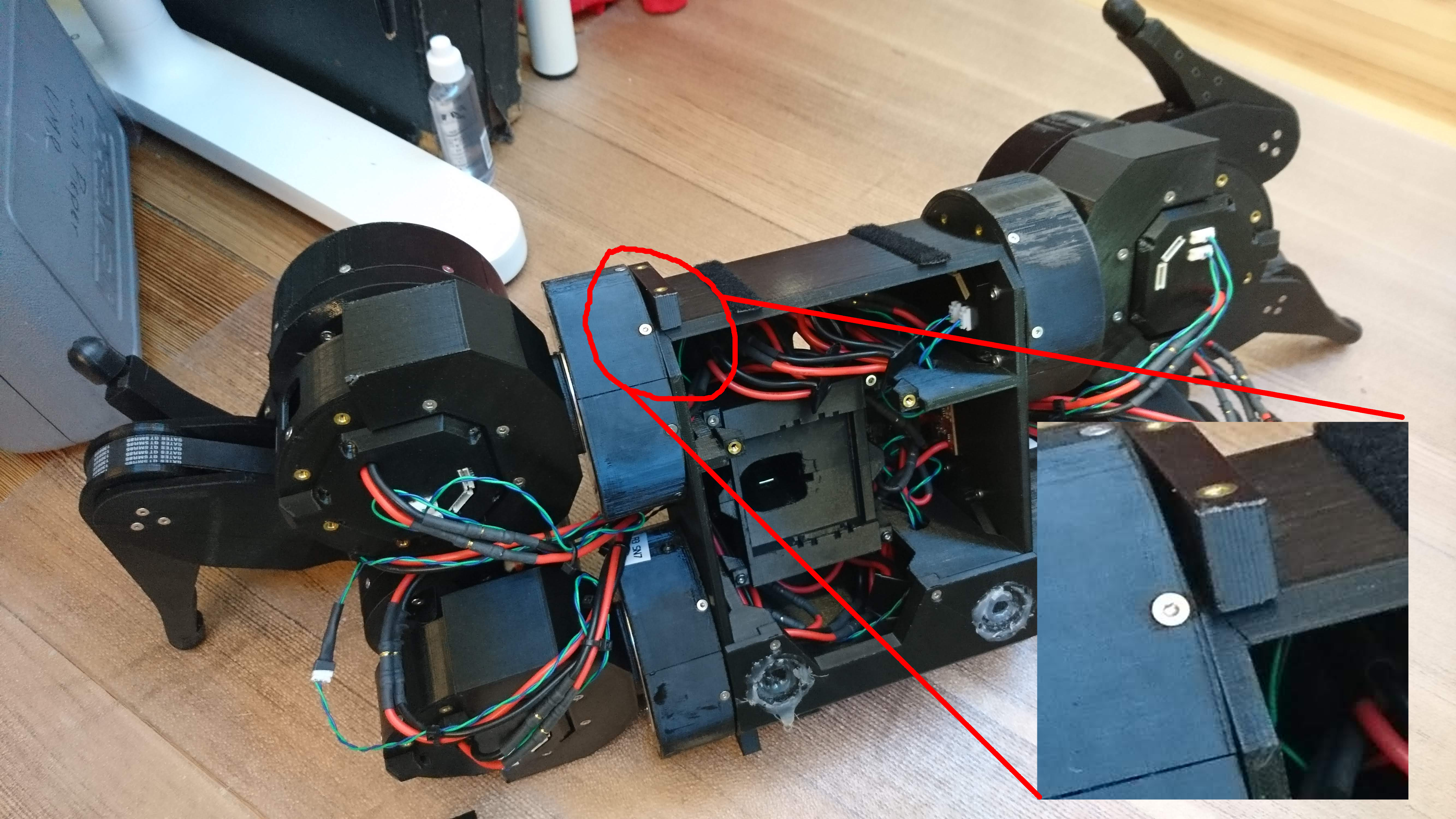
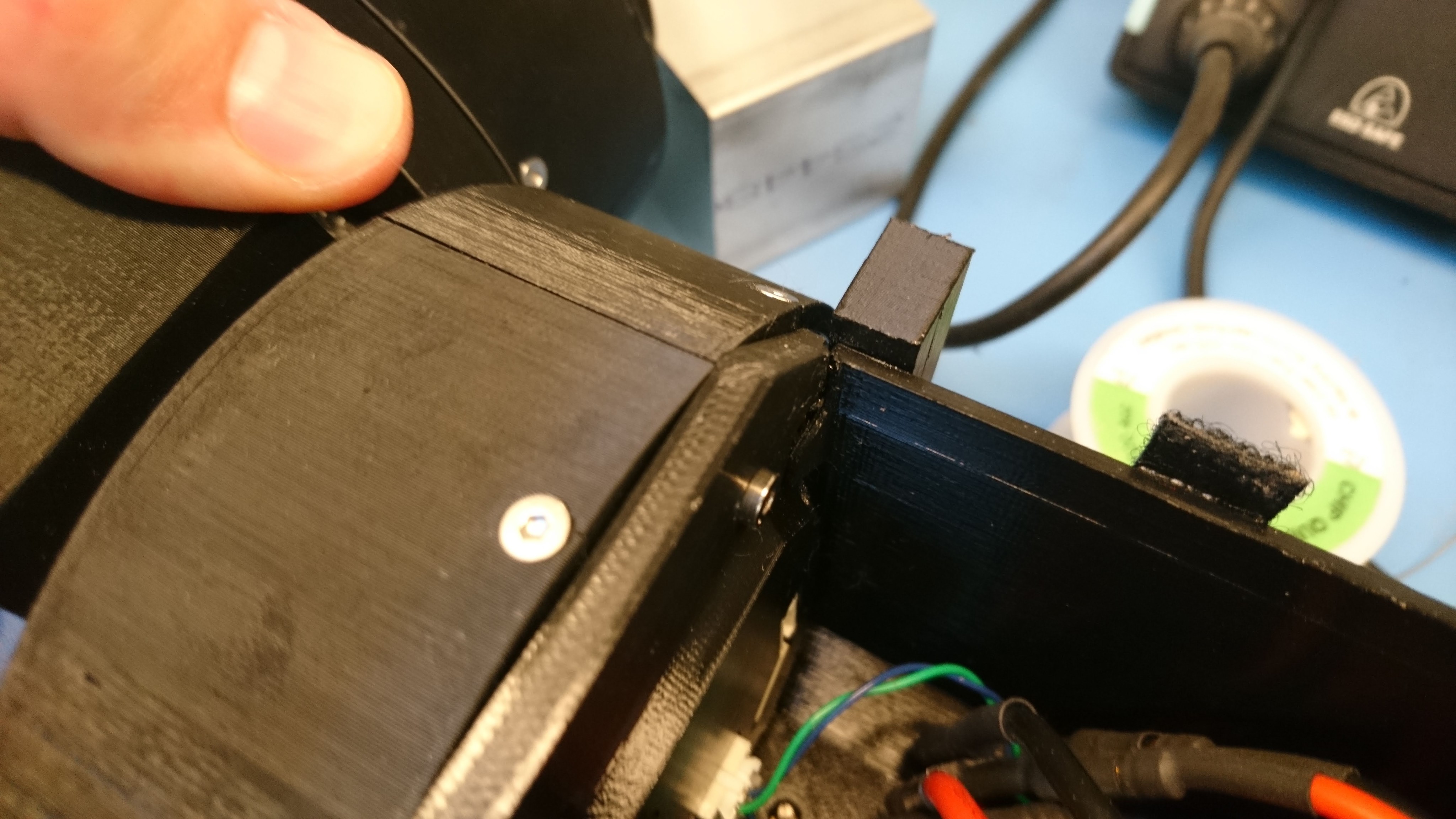
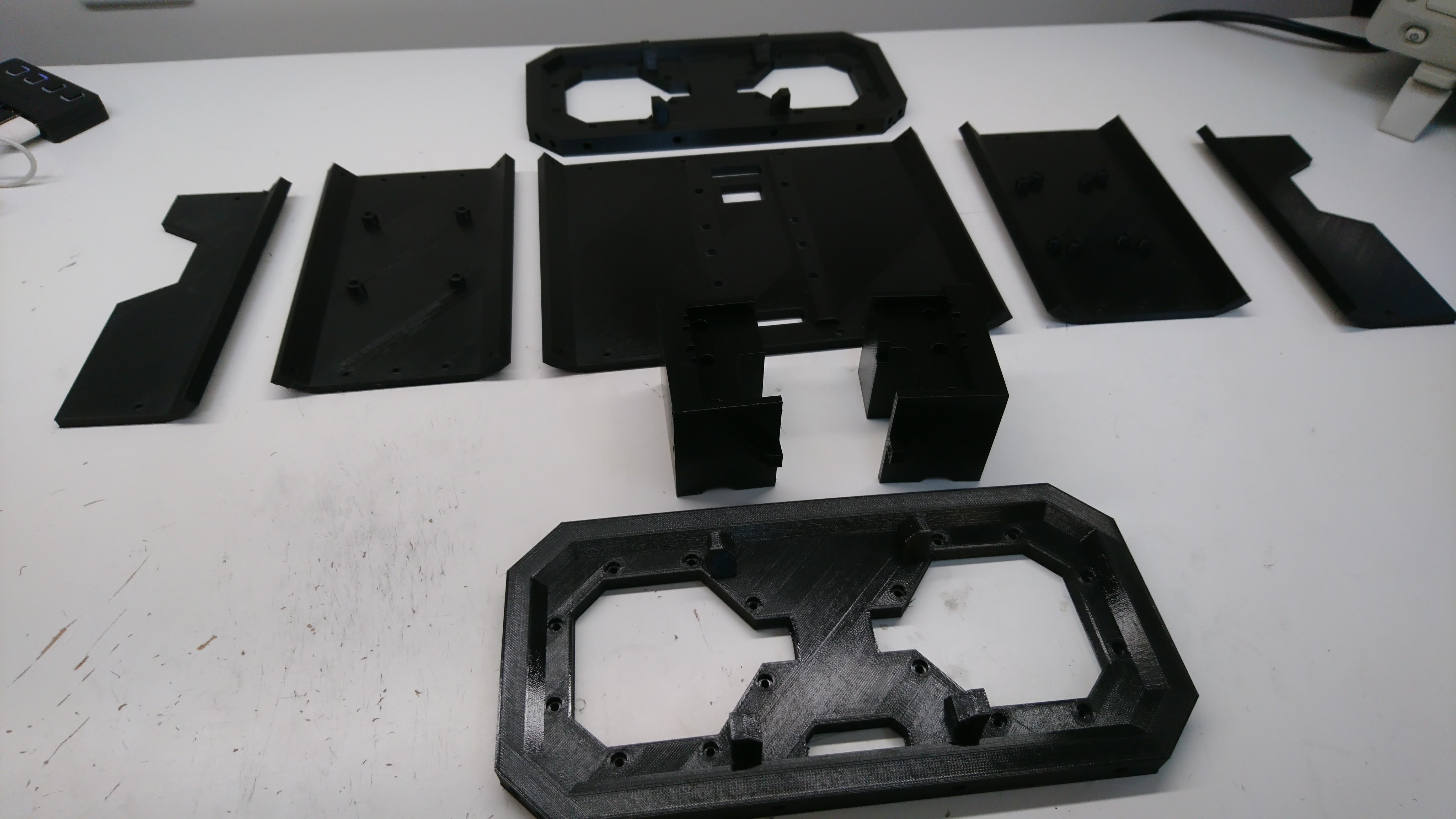
Another of the tasks I’ve set for myself with regards to future Mech Warfare competitions is redesigning the turret.  The previous turret I built had some novel technical features, such as active inertial gimbal stabilization and automatic optical target tracking, however it had some problems too.  The biggest one for my purposes now, was that it still used the old RS485 based protocol and not the new CAN-FD based one.  Second, the turret had some dynamic stability and rigidity issues.  The magazine consisted of an aluminum tube sticking out of the top which made the entire thing very top heavy.  The 3d printed fork is the same I one I had made at Shapeways 5 years ago.  It is amazingly flexible in the lateral direction, which results in a lot of undesired oscillation if the base platform isn’t perfectly stable.  I’ve learned a lot about 3d printing and mechanical design in the meantime (but of course still have a seemingly infinite amount more to learn!) and think I can do better.  Finally, cable management between the top and bottom was always challenging.  You want to have a large range of motion, but keeping power and data flowing between the two rotating sections was never easy.

quad A1 leg updates

When I first designed the full rotation leg, I didn’t fully appreciate the importance of torque in the knee joint.  Despite the fact that my first force based IK showed that when the legs are immediately under the body, the knee joint carries the entire load of the robot, I still managed to not add any reduction there.

The initial design used a 1:1 ratio, because that allowed me to use the same single piece 3d printed gear design I had used before.  A 28 tooth gear with 5mm pitch resulted in a gear that was larger than the output plate on the qdd100 servo, so it could just be bolted directly on.  To work with a smaller number of teeth, I had to split the gear into two parts, connected by pins, as the gear is now smaller than the qdd100 output plate.

3D printed camera mounting bracket

To help get some better overhead camera shots, I made a simple bracket that I could bolt to my over-desk bookshelves.  It just has a 20mm tube on it that various camera attachments can be bolted to:

dsc_0256dsc_0257

Here’s to more camera angles!

Final lower leg assembly

After casting the feet, the final step was to join the lower leg with the 3d printed foot bracket.  This I just did with some slow cure epoxy.

dsc_0280

It seems strong enough for now, I was able to manually apply 10kg of load to a single leg while perfectly horizontal with no signs of stress, which should be good enough for a 4g 4 legged jump.

All the legs (and a spare) are now assembled with belts and a lower pulley ready to go on a robot!

Casting feet

Previously, I described the overall plan for my improved foot.  To make that work, I needed to cast a 3d printed part into the squash ball such that it would likely stay attached during operation, be suitable rigid and yet damped, and do so repeatably.

To start with, I used a random single yellow dot squash ball with a hole cut in one side using a pair of side cutters.  For the casting foam, I just used Smooth-On Flex Foam-IT 17, which is what Ben Katz originally used at least.  Initially I just mixed up a batch, poured it in to a random level, stuck my bracket in and hoped for the best.

quad A0 - Improved foot design

As mentioned long ago in my post on failing more gracefully, it was obvious I wanted to strengthen the lower leg and foot mechanism to remove the point of failure observed there.  For now, I’m attempting to basically copy the original Mini-Cheetah foot principle, although with more 3d printing and less machining.

20200211-mk2-foot

The basic idea is to print the entire lower leg in a single go laying on its side, so that delamination is unlikely.  The foot bracket will be cast into a squash ball, then epoxied onto the lower leg.

mk2 leg knee stud

One of the parts on the original quad A0’s leg that was prone to failure was the “knee stud”, a little cylinder that acted as the mating interface between the upper leg and the lower leg.  It directly attaches to the upper leg, and has bearings that ride between it and the lower leg.  The entire tension of the leg belt is born in shear by this part.

20200206-knee-stud

In the mk1 leg, this part was 3d printed with heat set inserts used to form the threaded holes.  This mostly worked, although occasionally the stud could shear along the 3d printed lamination lines.  Thus, for the mk2 leg, I’m making this part out of 6061.

fdcanusb enclosure

To get ready for initial limited production of the fdcanusb I wanted to make some kind of enclosure so that you didn’t have to just grab the raw PCB and risk ESD failures.  I also wanted to be able to expose the status LEDs without having to do a window or anything else with multiple materials.

So for now, I just used a translucent PETG print, with light pipes and a thin wall above each of the LEDs.  The result isn’t too bad, you can clearly see the status LEDs and it feels plenty rugged for desk work.

quad A0 chassis v2 - final assembly

In the last post in this series, I conducted a fit test on the new chassis.  After my ignominious belly-flop, I now had a more urgent need to complete the switch.

A busted robot

A busted robot

An even bigger close-up

An even bigger close-up

The chassis cracked in the corner, completely separating.  Doing anything more with this chassis was likely to result in many more things breaking very quickly.

Build process

So, here are the photos as I put everything together.

quad A0 chassis v2 - construction

After CADing up the second revision of the chassis, I set to work with the 3d printer and printed up all the pieces.

dsc_1575

There were a few minor post-modifications I had to make, which were all much faster than printing the pieces again.  All the holes for M3 bolts were slightly undersized, so I drilled them out.  The battery holder had a channel to let the power wires out, which inexplicably terminated before reaching the edge of the holder.  I also had to install all the heat set inserts.