Archives: 3dprint

New Project: Juggling Robot

I’ve been looking for a new motor control project to tackle that is both interesting, and a bit more unique than another Ascento clone. Looking around, I was surprised at the current paucity of robots capable of more advanced juggling feats. There are quite a few that can manage 3 balls, and nearly none I’ve found that can manage more, with the exception of Nathan Peterson’s inclined ball roller. I figure that I have access to lots of factory second moteus controllers, which are capable of quite demanding control applications, so I should be able to put something together.

5 Side PCB Test Fixture

If you look around online, there are lots of examples of PCB test fixtures used to perform end of line testing. In the low to medium volume scale, nearly all of these are either clamshell or 2 side affairs, where probe pogo pins or interfaces are connected to the bottom and top of the board.

When developing the moteus-n1, one of the challenges was the number of right angle board edge connectors it has. Those right angle connectors are what allow it to maintain a very low overall stack height when installed in applications, but are also much harder to perform testing on, since by definition the access points are not vertical. On the base n1, there are 6 total right angle connectors, 2 on each of 3 sides, and future variants may have additional bottom side CAN and power connectors populated to make 8 total right angle connectors.

Working on a new leg for the quad A1 - Part 1

I’m going to try something new for this effort, and instead of making a bunch of blog posts culminating in a video, I’m going to make a bunch of intermediate progress videos. They may, but may not, culminate in an overview blog post. Here’s the first!

Gear testing fixtures

The qdd100 servo uses a planetary geartrain as the transmission reducer. This consists of an outer ring gear, an inner sun gear connected to the rotor as the input, and 3 planets connected to the output. The tolerances of these gears directly impacts the performance of the servo, namely the backlash and noise.

To date, I’ve been hand-binning these and testing each servo for noise at the end of production. To make that process a bit more deterministic, and with less fallout, I’ve built up a series of manual and semi-automated gear metrology fixtures to measure various properties of the gears.

New machine(s) day, more Prusas

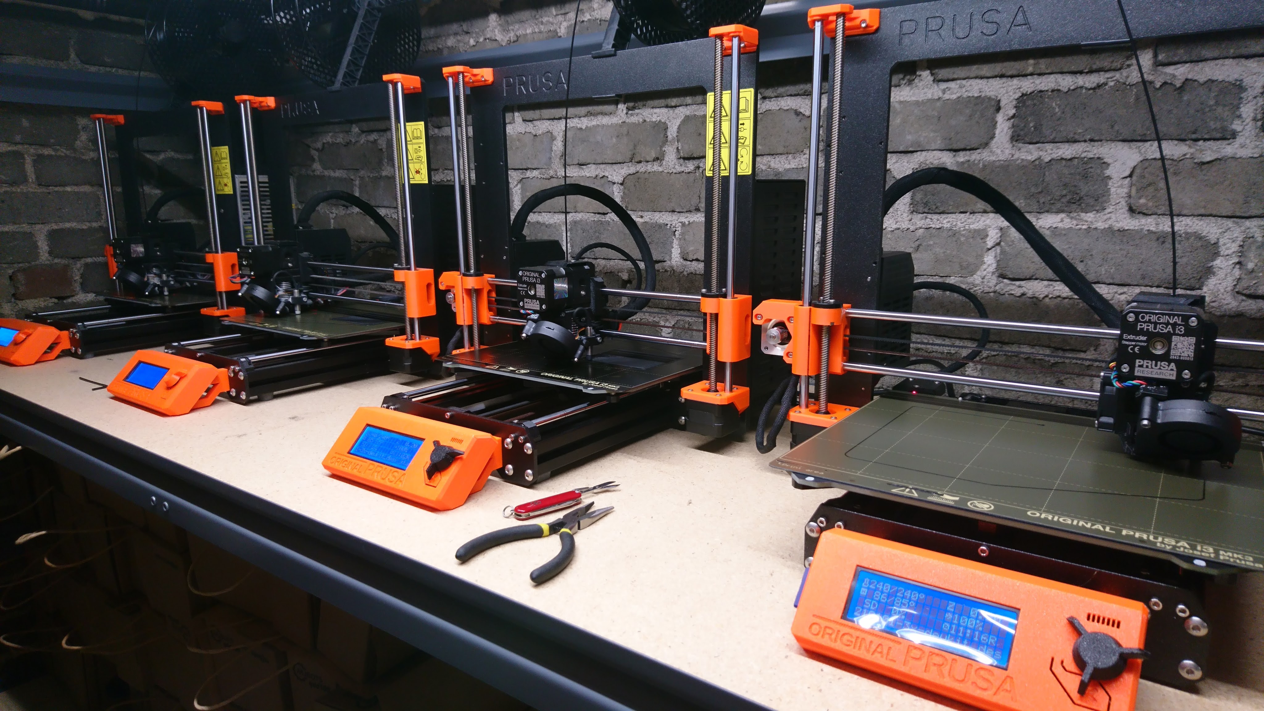
This is somewhat belated, but only recently have I actually gotten them all set up in the desired configuration. Welcome to the newest members of the mjbots factory line, another 2 Prusa MK3Ss! That makes 4 total, now all neatly lined up in a row:

The first two have had a greater than 60% duty cycle over the 3 years I’ve had them, and situations kept coming up where I was blocked on 3d printer bandwidth. For now at least that need is sated.

Microscope mount

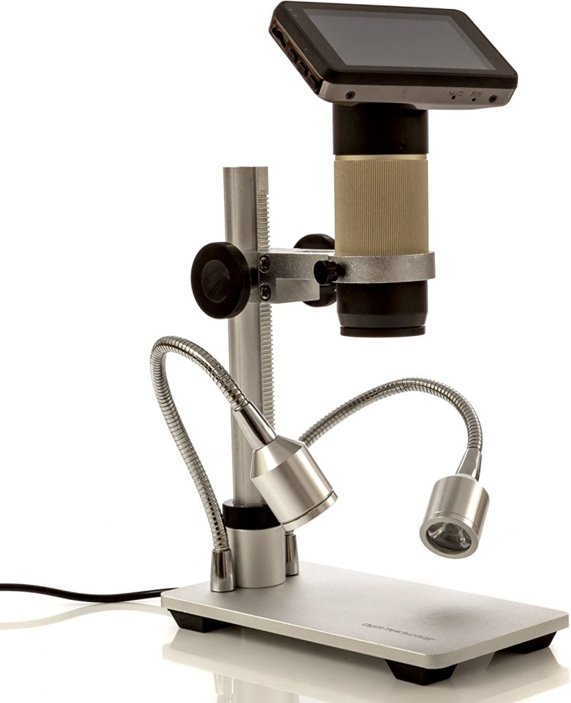
I’ve been using a relatively inexpensive microscope for SMD soldering work for some time, connected via HDMI to a 24" monitor.

For the price, I’m definitely happy with it, but as I’ve been doing more soldering work, I’ve become less happy with the mounting stand. The arm it mounts to often does not reach far enough to get the optics over the part of the board in question, or the base is too tall or wide to fit under it. If you want to examine something from the side, you have to tip the entire base over. I have resorted to spinning the microscope around and counterbalancing the base with a large weight, which works for some definition of “works” but only improves the reach by a little bit.

Another foot failure

The first feet I built for the quad A0 lasted for maybe an hour of walking before snapping off. The current design, has been much more robust - completing a lot of intensive walking and jumping. However, all things must fail:

Looking at the failure, I was surprised I used so little material in the region in question. For now, I just made it 4x thicker and we’ll see how long that lasts, although ultimately it may need to be a different design or machined instead of 3d printed.

quad A1 chassis updates

I finally got around to fixing a number of minor glitches in the quad A1’s chassis recently.

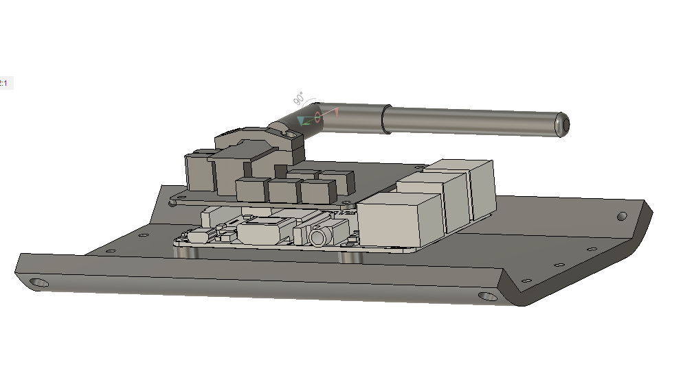
1. The raspberry pi is now far enough away from the left panel that you can connect the HDMI if you choose.

20200506-rpi_mounting

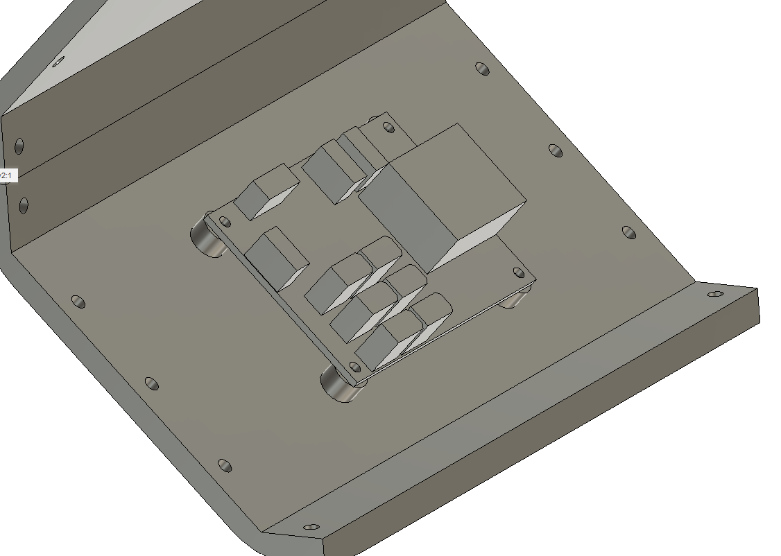
2. I no longer have vestigal studs for the pre quad A0 junction board on the other side.

20200506-power_dist

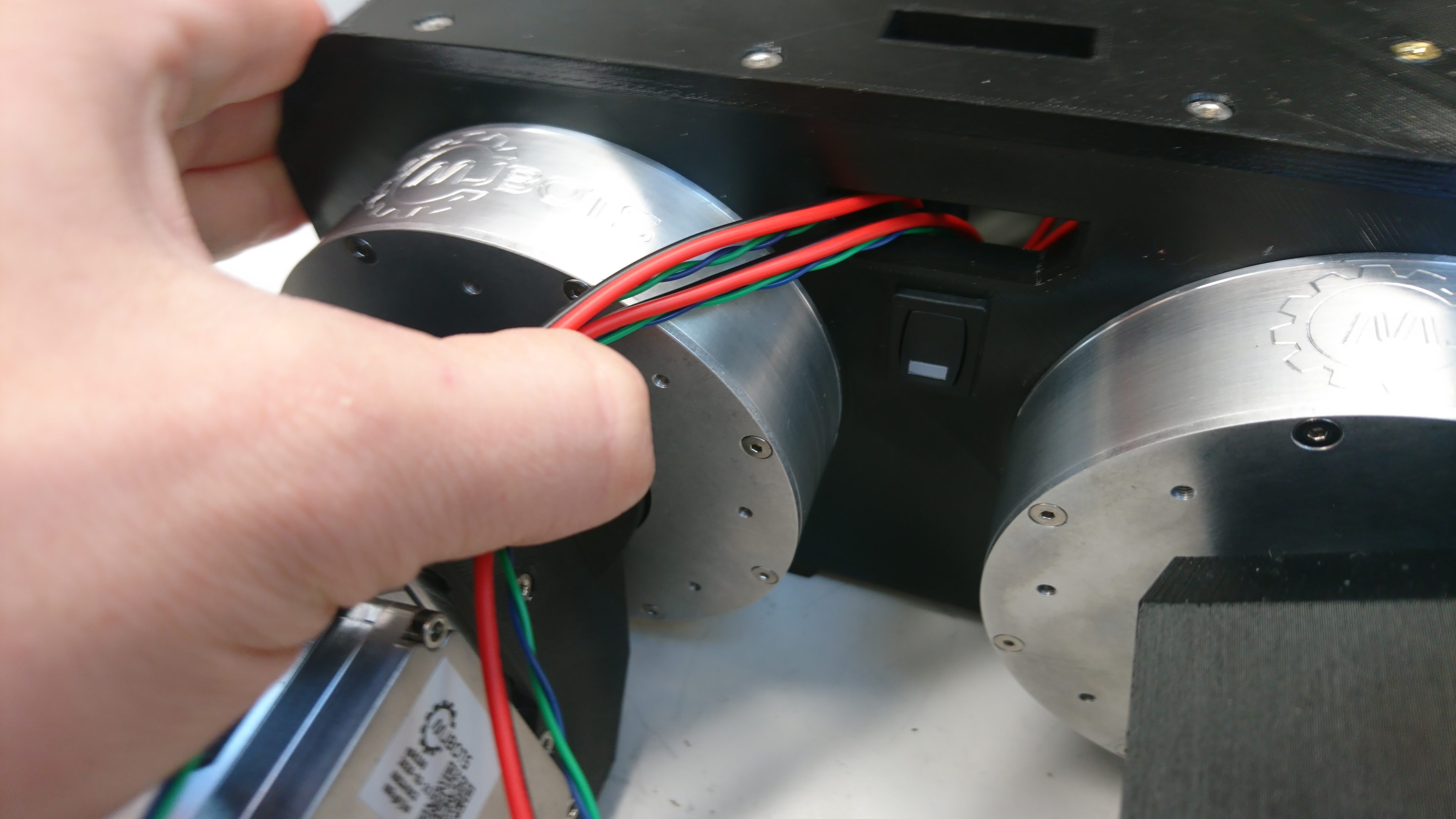
3. The switch got moved down to between the legs.

dsc_0631