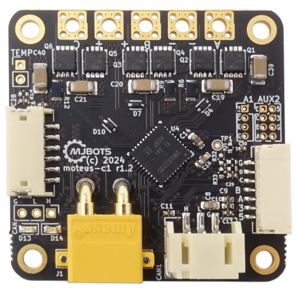
moteus-n1 available now!
This is a short and sweet post. The moteus-n1 as previously announced in beta form is now officially available at mjbots.com!
Here is yet another new product announcement! In the same line as the new pi3hat, here is a new minor revision of the power_dist, the r4.5b:
The changes are largely the same as for the new pi3hat:
The input voltage range is extended from 10-44V, to 10-54V.
The CAN-FD port has +-58V bus fault protection, up from +-12V.
Additionally, the measurement noise of the output current has been improved from 300mA to approximately 30mA.
Implied by my previous writeup on pin selection for external connectors, we’ve got a new variant of the moteus controller to announce today in beta form, the moteus-n1!
This variant is intended to be more feature-full, higher performance (and higher cost). Here are some bullet points of the biggest differentiators with r4.11:
moteus n1 | moteus r4.11 | |
---|---|---|
Price | $159 USD @ qty 1 | $104 USD @ qty 1 |
Size | As small as 46mmx46mmx8mm with optional back connectors omitted. 58% of the volume, 87% of the top down footprint size of r4.11 | 53x46x12mm |
External Peripherals | Each of the auxiliary connectors supports SPI, UART, ADC, SW & HW Quadrature, Hall sensors, and I2C. 5V and 3.3V is provided on each connector to power peripherals (100mA for each voltage available combined between both connectors). I2C pullups are configurable on each connector. All 4 pins on AUX2 are 5VT, the two non-SPI pins on AUX1 are 5VT. | ENC (AUX1) supports SPI, Hall and ADC. ABS (AUX2) supports UART and I2C and are both 5VT. |
RS422 | Built in RS422 transceiver for communicating with RS422 / BiSS-C encoders (BiSS-C / SSI not yet supported in software). | None |
Voltage | 8-54V, 48V nominal | 8-44V |
Peak Output | 100A output phase current, 1200W | 100A output phase current, 500W |
Continuous Output | 9A output phase current ambient, 18A w/ thermal management | 11A output phase current ambient, 22A w/ thermal management |
CAN fault tolerance | 58V bus fault tolerance | 12V bus fault tolerance |
Power Connectors | Solder pads for DC bus input, one always present XT30, one optional XT30 | 2x XT30 |
The short form is that the n1 does not really expand the set of motors that can be usefully driven, but does enable operation in 48V systems, is more compact and electrically robust and provides significantly improved external peripheral support.
moteus r4.11 has two external connectors, the ABS connector (AUX2) and the ENC/AUX1 connector. The ABS connector was designed initially just to have 2 I2C pins. The ENC connector just has the random pins that were used for the onboard encoder SPI plus one more. Thus the range of external accessories that can be connected is somewhat haphazard and not necessarily all that useful.
When working on a more ground up revision of the controller, I wanted to improve that situation to expose more connectivity options on still a relatively limited connector set. The idea was to use 2 connectors, one which has 5 I/O pins and the other with 4 I/O pins. The onboard encoder SPI would still be accessible on the larger connector to use for at least one external SPI encoder, but how much other functionality could be crammed into the remaining pins? To start, lets see what possible options there are in the current firmware and supported by the STM32G4 microcontroller that moteus uses:
I’m excited to announce a minor upgrade to the mjbots pi3hat product line, the pi3hat r4.5!
This has a few upgrades over the old r4.4b:
The input voltage range is expanded from 8-44V to 8-54V.
All CAN-FD ports have +-58V bus fault protection, up from +-12V.
0.1" pin headers are present for the Raspberry Pi I2C, UART, and for 3.3V and 5V outputs
Check it out at mjbots.com today!
With the release of more flexible I/O support, the moteus controller auxiliary port can be used to monitor encoders using an onboard UART. Now, with firmware release 2023-02-01, those UART pins can be used as an arbitrary logic level serial port controlled by the application! Let’s see how to use it below.
First, you will need to look at the pin configuration table to find pins that support UART functionality, and configure them as UART in the “aux?.pins” configuration tree. Next, “aux?.uart.mode” should be set to “kTunnel”, along with the desired baud rate. That’s it on the configuration front.
The moteus controller, when it implements its control algorithms, uses the internal RC oscillator of the onboard STM32G4 microcontroller to calculate things like velocity and to advance position over time. Typically, this is accurate to within 0.5% which is more than sufficient for most applications. However, there are cases where it does matter.
One common case is when multiple moteus controllers are operated together, and either the relative velocities of the controllers must match closely, or the time required to complete long trajectories must match closely. For example, if a trajectory would take 100s to complete, then a 0.5% difference in clock rate between two controllers would result in one completing 0.5s before the other.
Partly to celebrate moteus controllers being back in stock and partly because a lot of important work has backed up, we’ve just released a new firmware version for moteus (2023-02-01) that has a little bit of something for everyone. Future posts will examine some of these features in more detail, but for now you just get the bullet list:
Support sending and receiving arbitrary data from a UART configured on either of the auxiliary ports
While testing moteus controllers, it is often necessary to experiment with high power conditions. For short durations, any decent sized brushless motor can work, as the windings have a non-zero thermal mass and take a little bit to warm up. However, when testing at high power for extended duration, it can be hard to find a way to get rid of all output energy. Even blowing a fan directly onto a motor only gets you so far when you are trying to get rid of 1kW.
Here’s a not-so-brief story about troubleshooting a problem that was at times vexing, impossible, incredibly challenging, frustrating, and all around just a terrible time with the bare-metal STM32G4 firmware for the moteus brushless motor controller.
First, some things for context:
moteus has a variety of testing done on every firmware release. There are unit tests that run with pieces of the firmware compiled to run in a host environment. There is a hardware-in-the-loop dynamometer test fixture that is used to run a separate battery of tests. There is also an end-of-line test fixture that is used to run tests on every board and some other firmware level performance tests.