mjbots will be at FAB16 in Somerville - Saturday August 14th
Check out the quad A1 and all the mjbots products at the FAB16 festival in Somerville, MA this Saturday August 14th from 10am to 4pm (with a rain date on Sunday).

Check out the quad A1 and all the mjbots products at the FAB16 festival in Somerville, MA this Saturday August 14th from 10am to 4pm (with a rain date on Sunday).
I’m going to try something new for this effort, and instead of making a bunch of blog posts culminating in a video, I’m going to make a bunch of intermediate progress videos. They may, but may not, culminate in an overview blog post. Here’s the first!
The qdd100 servo uses a planetary geartrain as the transmission reducer. This consists of an outer ring gear, an inner sun gear connected to the rotor as the input, and 3 planets connected to the output. The tolerances of these gears directly impacts the performance of the servo, namely the backlash and noise.
To date, I’ve been hand-binning these and testing each servo for noise at the end of production. To make that process a bit more deterministic, and with less fallout, I’ve built up a series of manual and semi-automated gear metrology fixtures to measure various properties of the gears.
I’ve been doing some machining on the Pocket NC lately to prototype some “design for manfacturing” improvements. Some time ago Q at Pocket NC posted that early versions of the v2-50 had a spindle power limit that they later decided wasn’t necessary. My v2-50 was pre-ordered at the launch, so had said limit. There was a procedure for removing it in later versions, which just required removing a single SMT resistor.
For most of mjbots’ existence, all of our products were labeled with a dependable, if lackluster, Brother P-Touch label maker. In line with other packaging improvements, I recently upgraded that labeling setup to bigger, higher resolution, and full color!
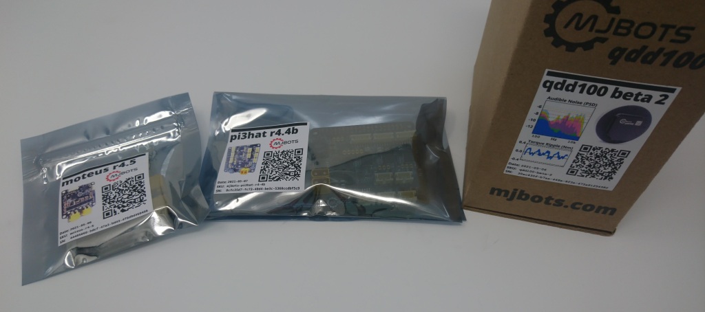
This is using an Epson TM-C3500, which I had expected to operate directly from my Linux based test fixtures. However, upon receiving it, discovered that alas only Windows drivers were available. Thankfully, it wasn’t too bad to print from python in a simple way as long as you manually select the media type from the Windows dialogs. Thus I made up a simple Flask app to receive label images over HTTP and print them. That runs on a Windows computer, and the test fixture applications just POST their label images to it.
The pi3hat, among other things has 5 CAN-FD ports. You can use them to drive a lot of moteus servos, but they are perfectly fine CAN-FD ports generally. The C++ library has always been able to send and receive arbitrary frames (and recently at arbitrary bitrates), but the python interface was lacking, only exposing a portion of this functionality.
As of version 0.3.11, the python library (pip3 install moteus-pi3hat) now exposes everything you need to be able to send and receive arbitrary CAN frames from any of the ports, as well as configure all the timing options for waiting for responses from slave devices.
This is somewhat belated, but only recently have I actually gotten them all set up in the desired configuration. Welcome to the newest members of the mjbots factory line, another 2 Prusa MK3Ss! That makes 4 total, now all neatly lined up in a row:
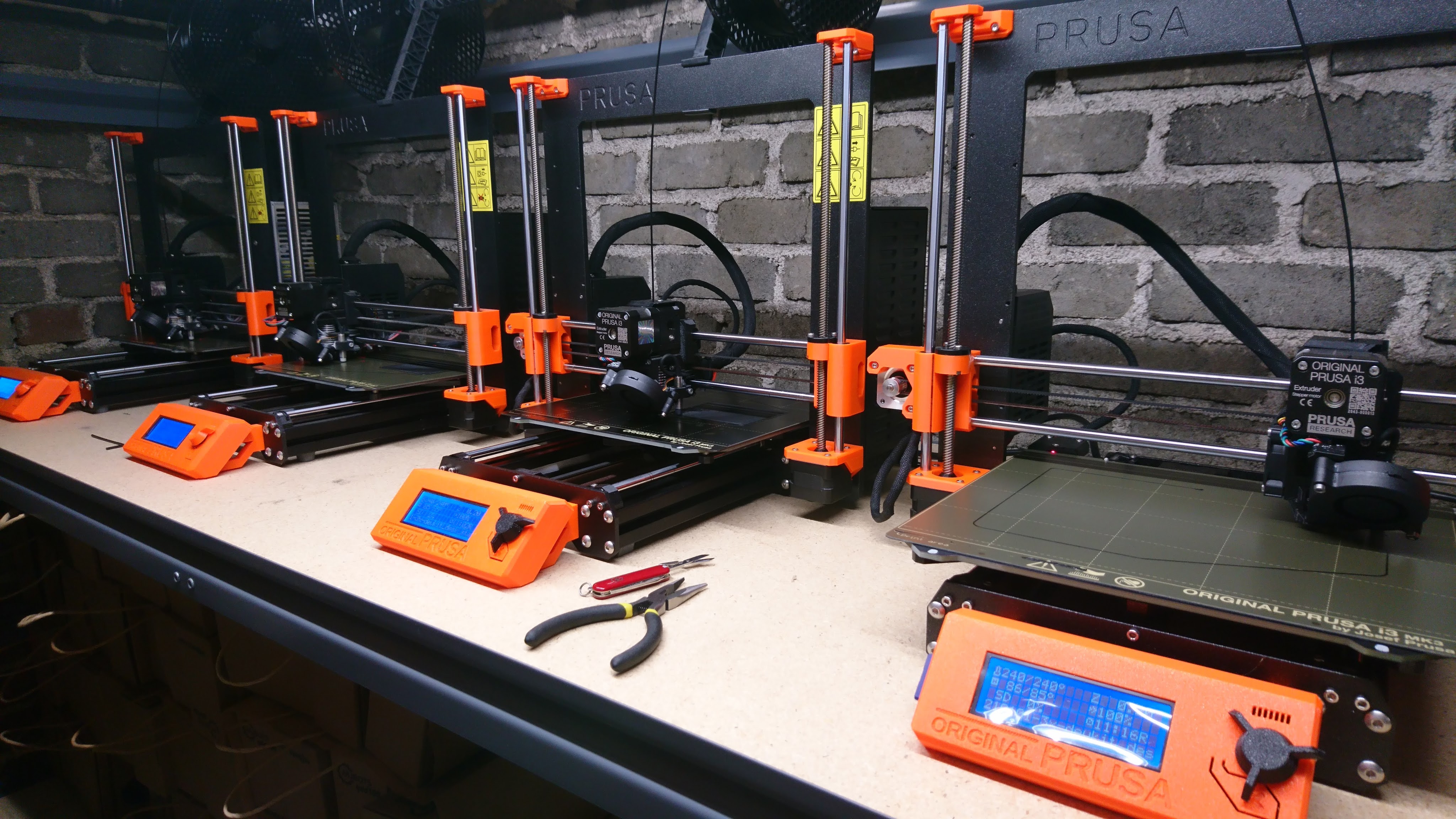
The first two have had a greater than 60% duty cycle over the 3 years I’ve had them, and situations kept coming up where I was blocked on 3d printer bandwidth. For now at least that need is sated.
TLDR: moteus can now filter the encoder, resulting in less audible noise. Use firmware version 2021-04-20 and ‘pip3 install moteus’ version 0.3.19, then re-calibrate to get the benefits.
The moteus controller uses an absolute magnetic encoder to measure the position of the rotor. It uses this knowledge to accurately control the current through the three phases of a brushless motor so that the desired torque is produced, i.e. “field oriented control”. This works well, but has some downsides. One, is that magnetic encoders work by sensing the magnetic field produced by a “sensing magnet” that is somehow affixed to the rotor. This sensing process always introduces some noise, so that the sensed rotor position is never perfect.
In what probably won’t be the last time, mjbots.com now has a new version of the pi3hat due solely to component shortages!
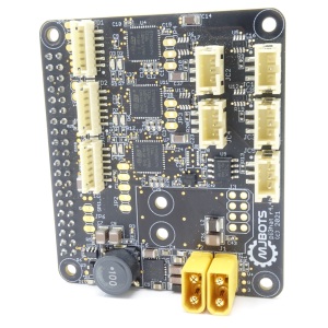
There are no top-level feature changes versus the previous r4.4. What is different is that the connector for the Raspberry Pi has reverted to the fixed height version that the r4.3 and earlier used, and the IMU is slightly better.
Happy building!
Since the first public release, moteus has always calibrated motors so that a positive command is equivalent to a fixed sequencing of the phase wires. That means that depending upon which order you solder the phase wires, a positive commanded velocity will result in the motor spinning either clockwise or counterclockwise.
As it turns out, since moteus has an absolute encoder that is immune to such vagarities, it is much more convenient to normalize the direction of rotation around the encoder rather than the phase wires. As of release 2021-04-26, and moteus_tool 0.3.22, that is exactly what moteus does.