How to build XT30 cables
People over in the mjbots discord frequently ask about how to build reliable XT30 cables, so I made a short video describing how I go about it!
People over in the mjbots discord frequently ask about how to build reliable XT30 cables, so I made a short video describing how I go about it!
This new release makes minor improvements to support for r4.8 moteus boards, notably it makes the Kv and winding resistance calculation more closely match that measured by r4.5 and decreases audible noise when controlling to 0 current or torque.
Get it from github: moteus 2021-09-19
Note, this does require a new version of moteus_tool to be able to flash over CAN, version 0.3.29. You can get it from pypi using any of the normal pip3 methods: https://pypi.org/project/moteus/
Yet another in the series on building a new leg for the quad A1:
A motor driver like moteus switches power to the phases of a brushless motor using a set of 6 (or possibly more), MOSFETs. The typical topology involves 3 high side N channel MOSFETs and 3 low side N channel MOSFETs arranged in 3 half bridges like this:
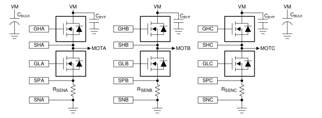
(example 3 half-bridge from DRV8353 reference manual)
Since the gates of these FETs need to be driven with potentially high voltages, and you never want the high side and low side to be on at the same time, typically a gate driver is used. For the moteus r4.5 and earlier controllers, the DRV8323 driver from Texas Instruments is what performs this function. This driver lets you configure the drive current for each of the gates for both operations, charging up the gate and discharging it. For high power drive systems, charging up or discharging the gate too fast can result in undesired transients like accidentally switching the other FET on due to capacitive coupling, or inductive ringing as the current starts moving through the FET instead of the body diode. If the gate charges too slowly, then the FET spends much of its time not fully on, which increases power dissipation in the FETs.
I’m excited to announce the release of moteus r4.8!
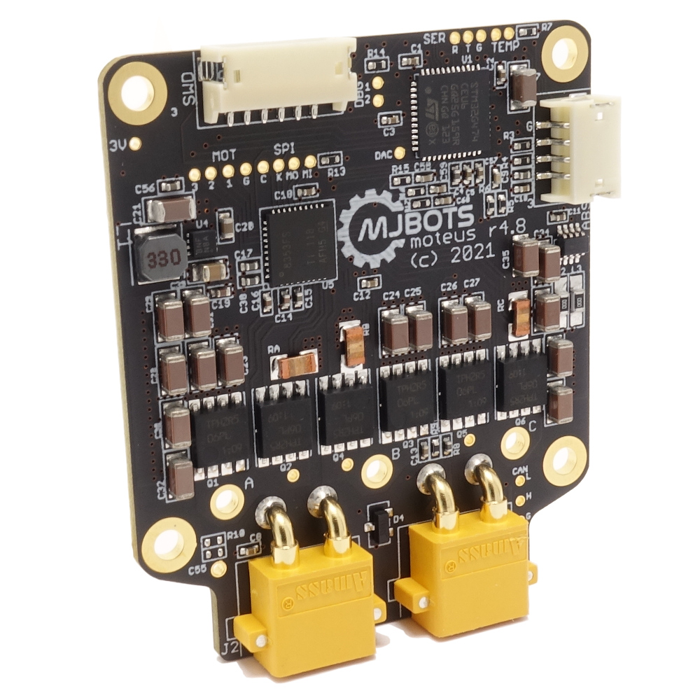
Due to the ongoing semiconductor apocalypse, this minor release uses some alternate components which were easier to source. It remains compatible with the r4.5 and r4.3 both electrically, mechanically, and with firmware.
For now, the biggest win is that the board and the devkit are actually in stock!
A secondary win is that external primary encoders are now supported, via an unpopulated connector pad on the backside of the board. I’ll write up more about that in a later post.
What happens if you accidentally write to address 0x00000000 on an STM32 microcontroller? Answer: usually almost nothing, because most linker scripts by default map a bank of flash there, and you can’t write to flash normally. The flash controller does notice and sets an error flag, but most applications aren’t exactly checking the flash peripheral’s error flags on a regular basis.
However, if you use the HAL to try and perform a flash operation, it doesn’t bother checking the error flags *before* trying to perform an operation. It just tries, and reports any errors it observes at the end. So, if you have an application that occasionally makes a spurious write to the zero address, and also performs flash operations, it will manifest as spurious failures of the flash operations.
In the spirit of my last post on the topic, here is another video-only update on a new leg design for the quad A1:
The moteus controller, communicates exclusively over CAN-FD for command, telemetry, and diagnostics. It will accept either standard or extended frames, and until now, the ID format in terms of bits looked like the following:
33333222222221111111100000000
43210765432107654321076543210
XXXXXXXXXXXXXQSSSSSSSDDDDDDDD
Where:
If the lower 8 bits matched the configured ID, all the X bits would be completely ignored and moteus would accept the CAN message as if it were destined for itself. This may not be super desirable, as it consumes nearly all of the available CAN-FD addressing space.
I and the quad A1 had a great time at the FAB16 festival in Somerville this past weekend. The robot got to do a lot of running around, it and I got to meet a lot of new people, and two bands showed up!
Here’s a video of the quad A1 and Spot hanging out trying tricks:
And here’s another one of a “dance off” (kinda) with the School of Honk band. Note that although both robots collapsed at the end of this video, the quad A1 got back up and kept dancing. (Spot wasn’t broken, they just didn’t want to right it when close-ish to people). Thanks to Kathleen and Josh from BD for inviting me into their area and for being such good sports!
The title says it all! Check out the quad A1 and friends there!