Archives: Features

Configurable sample point for fdcanusb/mjcanfd-usb-1x

CAN-FD communication has a number of configurable parameters in order to specify how long each bit period lasts, what amount of clock skew is permissible, and when to sample the physical layer to clock in each bit. For many CAN 2.0 applications, only the bitrate is configured and the sample point and skew parameters are left to a default. Optimizing them may be necessary if you want to control timing margins over a CAN bus with many hosts. Doing so is often not necessary though, as for CAN 2.0 different hosts can have different sample points and largely still interoperate.

AMT22 support

Here’s a short and easy to report new feature for moteus. Thanks to Eli Rutan, as of firmware release 2025-07-21, the same sky AMT22 SPI 14/12 bit absolute encoder (formerly CUI Devices), is now supported in moteus firmware. It requires a 5V supply, so can be used with the moteus-c1, moteus-n1 and moteus-x1 in all the ways other external SPI encoders can be used.

Both 12 and 14 bit single turn encoders are supported. Multi-turn variants can be used, although moteus does not use or need the multi-turn functionality.

Output limit reason reporting

There are many configurable values and internal firmware limits in the moteus brushless motor controller that result in the output current being less that would exist in an ideal system or less than what was commanded. To date, the only way to know if any of these factors was resulting in limiting behavior was to know all of the possible limiting factors, and look at factor specific diagnostic values one by one to see which was the culprit. Now, as of firmware release 2025-07-21, moteus will report exactly which feature is limiting the output at any given point in time, making that diagnostic process much simpler.

Read on for more details.

Improved hall effect encoder performance

moteus first added support for hall effect encoders way back in 2022, when many new encoder types were added. At that time, hall effect sensors were treated basically like any other encoder. However, because of their inherent low resolution, this resulted in them performing much worse than other encoder options, especially at low speed. In practice, very careful tuning of the encoder low pass filter was required to achieve useful performance and that performance would often only be valid in a narrow range of speeds.

Now, as of release 2025-07-21, moteus has a suite of new heuristics which drastically improve the performance of hall effect encoders at all speeds, and make them relatively insensitive to filter bandwidth selection. If you don’t care about the details, just upgrade your firmware following the instructions in the reference manual and be on your way! If you do care about the details, read on for more.

Automatic selection of voltage mode control

For some time now, moteus has supported operating in what is called “voltage mode control”. In that mode of operation, the current control loop of the Field Oriented Control process is short circuited. Instead of modulating the output voltage to achieve a desired current, instead it is assumed that there is no inductance and the desired voltage can be selected purely using the phase resistance and back EMF. This is a useful mode of operation anytime the output current range is small relative to moteus’s ability to sense it, often but not always with gimbal motors. The drawback of the mode was that:

  1. there is no torque control
  2. you had to know it existed
  3. you had to manually select it

However, as of release 2025-03-27 / pypi 0.3.77, moteus_tool will now attempt to automatically select voltage mode control if it looks like the motor is high resistance relative to the controller being used.

Moaar power!

Exciting news! All the existing moteus controllers in the world now have an upgraded default maximum power and upgraded rated maximum power as of release 2025-03-27! Depending upon the input voltage and PWM rate, sometimes nearly twice the amount. First, check out the comparison table, then the rationale:

Old default max / rated New default & rated
moteus-r4 340W / 450W 900W <= 30V, 400W >= 38V
moteus-c1 75W / 100W 250W <= 28V, 150W >= 41V
moteus-n1 340W / 1200W 2kW <= 36V, 1kW >= 44V

Background, why a power limit?

moteus brushless motor controllers drive 3 phase PMSM motors, accepting a DC input voltage, and outputting current to each of the 3 phases of the motor. It does so using MOSFET based switching, which alternately connects each phase to either ground, or the DC positive input. As that switching progresses, charge is either drawn, or replenished into, the onboard bulk capacitors.

MA600 encoder support in moteus

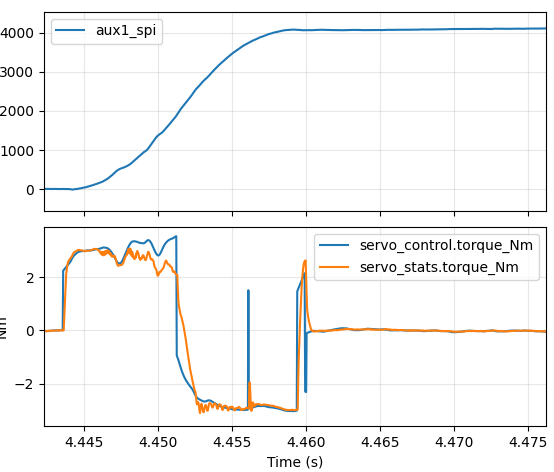
It’s time to announce support for yet another encoder type in moteus, this time the MA600 precision tunnel magnetoresistance (TMR) sensor. Compared to hall effect magnet angular sensors the MA600 has lower noise and less non-linearity. It has a SPI interface and operates from 3.3V. When used with moteus, it can be connected to AUX2 on moteus-c1 and moteus-n1, and to AUX1/ENC on moteus-c1, moteus-n1, and moteus-r4. Support is available in firmware version 2024-10-29 and newer.

On axis performance

To show what it is capable of, I mounted a small breakout board above an on-axis magnet attached to a mj5208.

Space vector pulse width modulation (SVPWM) for moteus

A permanent magnet motor controller like moteus has to, at the end of the day, apply voltages to the phase wires of a motor in order to induce currents. Those currents generate magnetic fields that push against permanent magnets in the rotor to make the motor move. I’ve looked at parts of this process before, see “Compensating for FET turn-on time”, but in this post we’ll look at an additional technique that can extend the effective modulation depth, thus increasing the maximum speed that a motor can be driven.

PWM output with moteus

Here’s a bit more in-depth discussion of a yet another new feature from moteus firmware release 2024-10-29: pulse width modulated output on auxiliary ports.

A pulse width modulated signal is a logic level signal of a fixed frequency, where the duty cycle, or width of the pulse, is changed or modulated to communicate a scalar value. Obligatory Wikipedia diagram below:

The new feature does what it claims to do, in that a subset of auxiliary pins can now be configured to output a PWM signal. If so configured, the duty cycle can be controlled using either the diagnostic or register protocol.

moteus configurable motor thermistors

When operating a moteus controller with a brushless motor there are two main things that can get hot: the FETs (field effect transistors) on moteus and the motor itself. By default, moteus has built in thermal throttling and fault detection if the FET temperature exceeds rated limits. In many configurations, the motor can be thermally connected to the moteus controller, so that the same FET temperature sensing can be used to prevent damage to the motor, but that isn’t always the case.