Measuring torque ripple
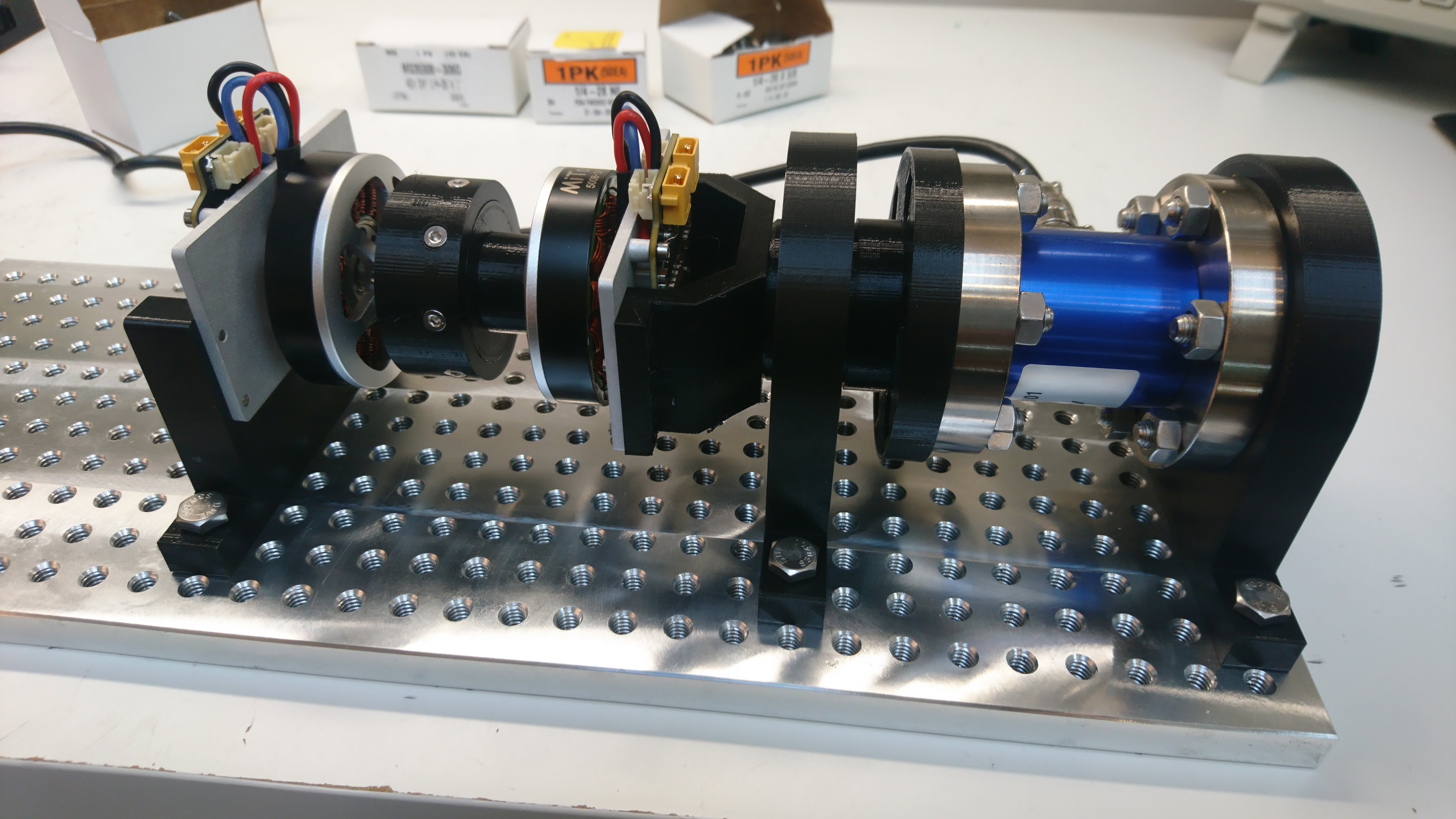
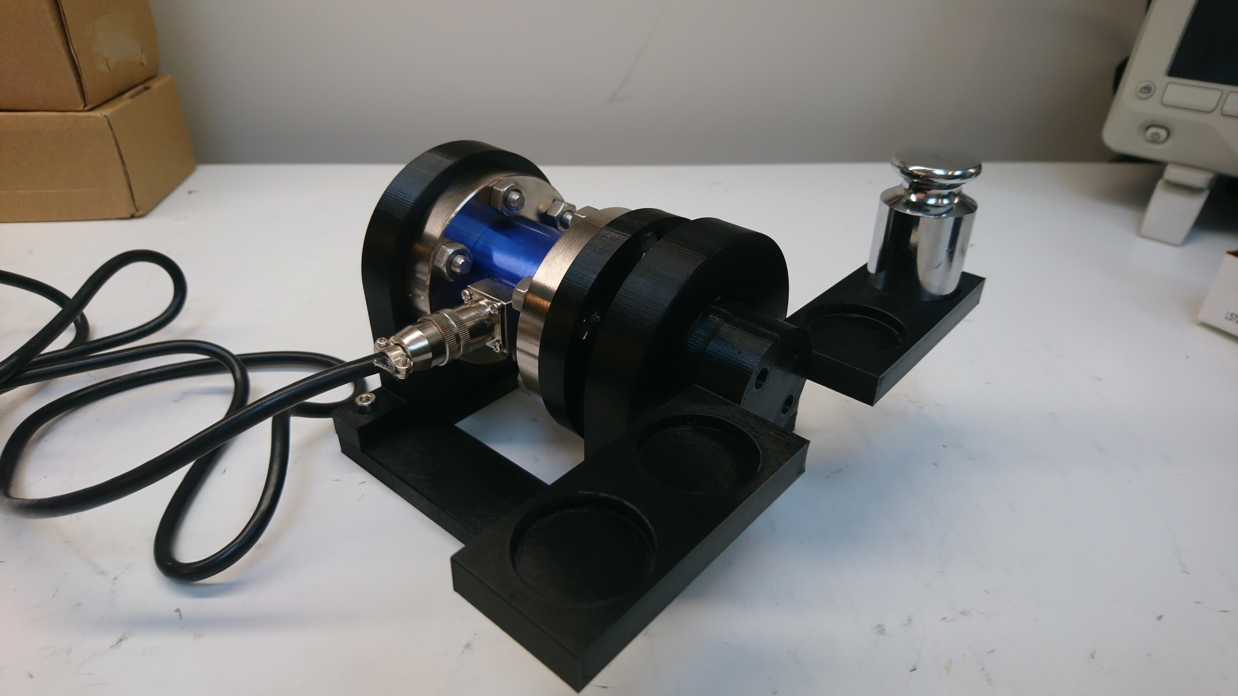
Recently I described some changes I made to improve the low speed torque ripple of the moteus controlle. I also built a dynamometer. I decided to use the dynamometer to quantify how much things had improved with the torque ripple, and to see how much room for improvement was left with any anti-cogging implementation.
Dynamometer script
Here, the test script is relatively simple. I have the “fixture” controller sweep at a very low velocity (0.01Hz) through a bit more than one full revolution using a relatively high I term in the PID controller to ensure that it really holds that position no matter what external torque is applied. Then, the “device under test” controller is just commanded either to be powered off, or in position mode with a pd gain of 0 and a feedforward torque. Then I can just measure the result from the torque transducer while this sweeps through a full revolution, and correlate the measured torque with the encoder position.