Nonlinear encoder compensation with no reference
This post is part of series examining how low-cost off-axis encoders can be incorporated into a moteus controlled motor system. For the history, see the previous entries: part 1, part 2, part 3, and part 4. We left off after having tuned the bias current trimming of the MA600 in order provide output from the encoder itself. When compared against a reference AksIM-2, that left an error profile that looks like:
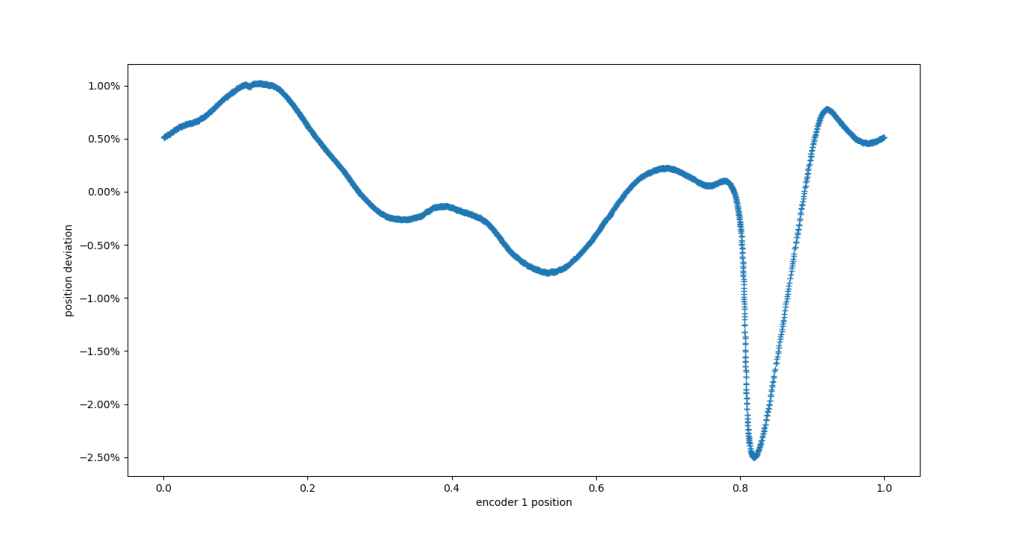
Position error with respect to AksIM-2 after BCT tuning