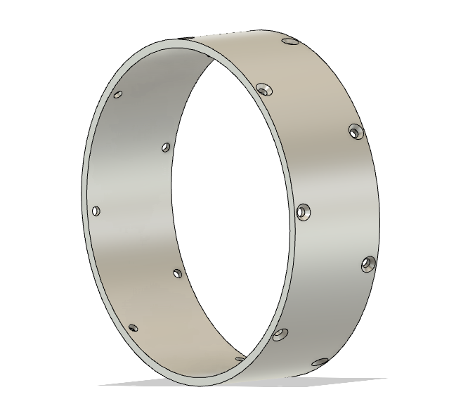
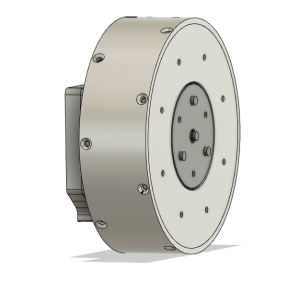
moteus servo mk2: Front housing
The front housing is the most complex machined piece in the moteus servo mk2, as it was in the mk1. It is relatively large and mates with many other components with the associated tight tolerance surfaces. For mk2, the front housing is even larger in diameter, but otherwise has the same basic features.
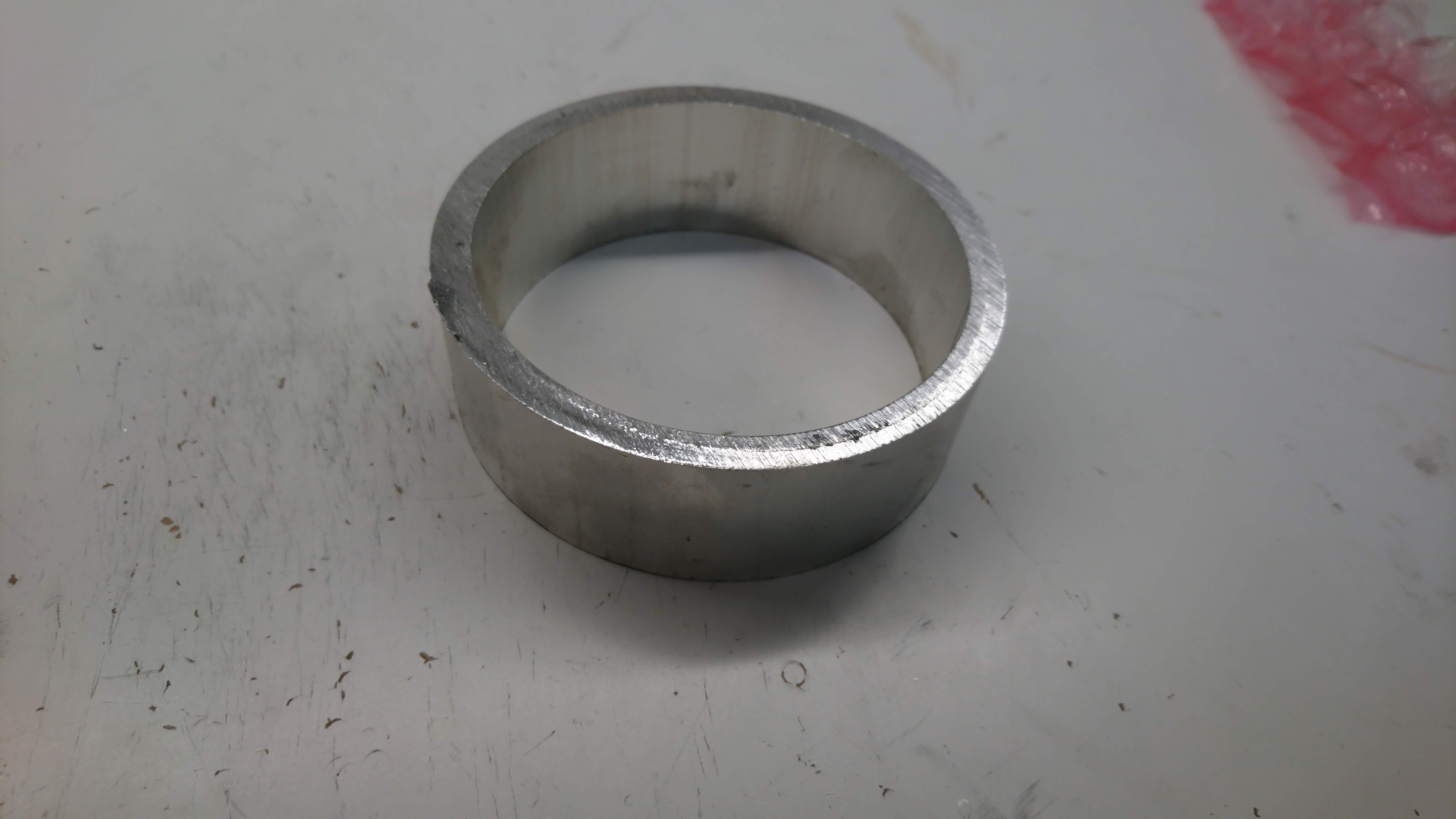
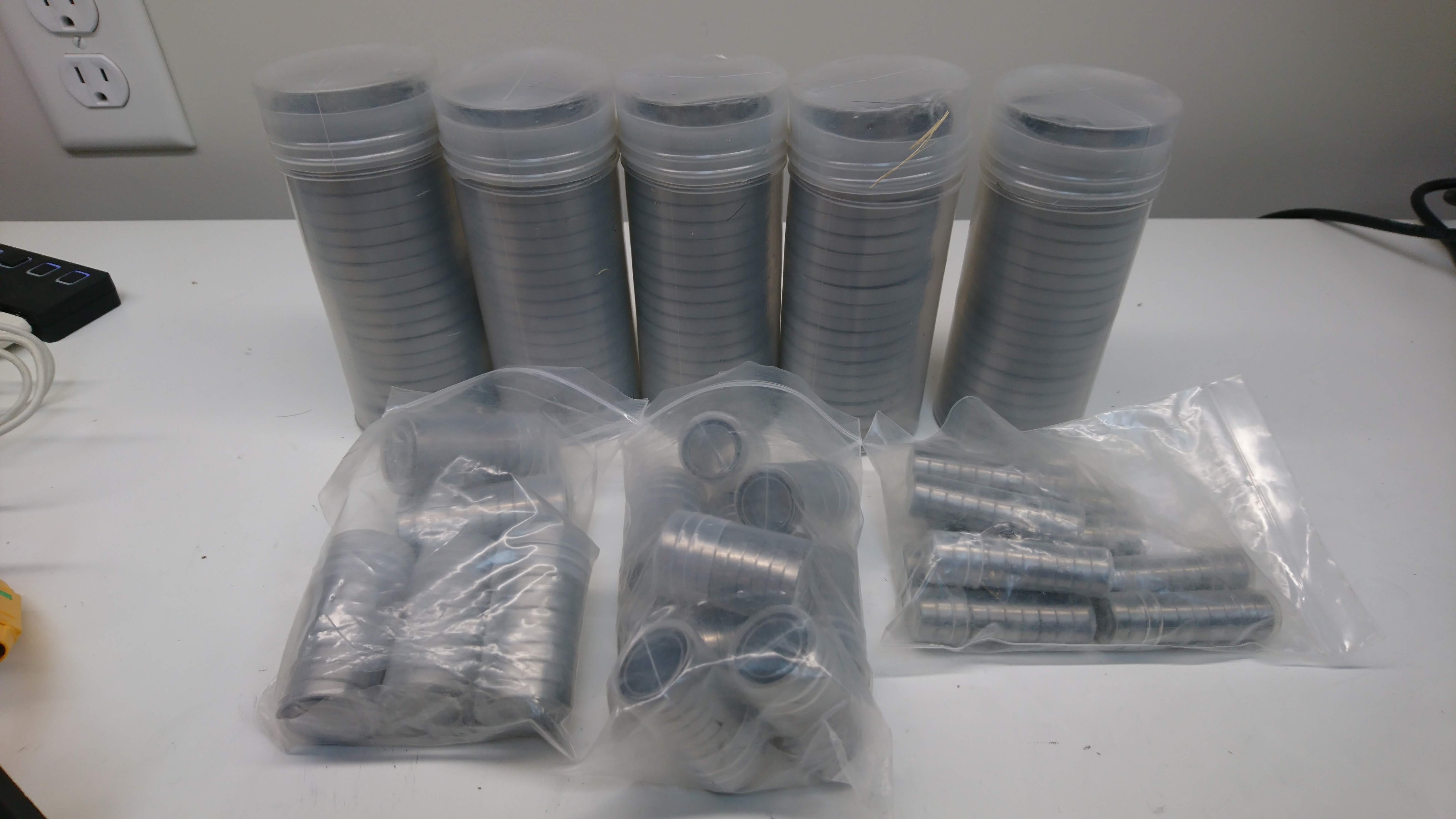
Manufacturing
Building a prototype of this was a real challenge given the tools I have available to me now. For mk1, I didn’t even try and just had Xometry build my prototypes, and was lucky enough that the first ones worked. My only CNC currently is the Pocket NC v2-50, which is just barely big enough to deal with this part, and has no convenient workholding that can be used for the stock. Also, it has a low material removal rate, such that starting from stock here would be prohibitively time consuming.