moteus servo mk2: Reduced weight test
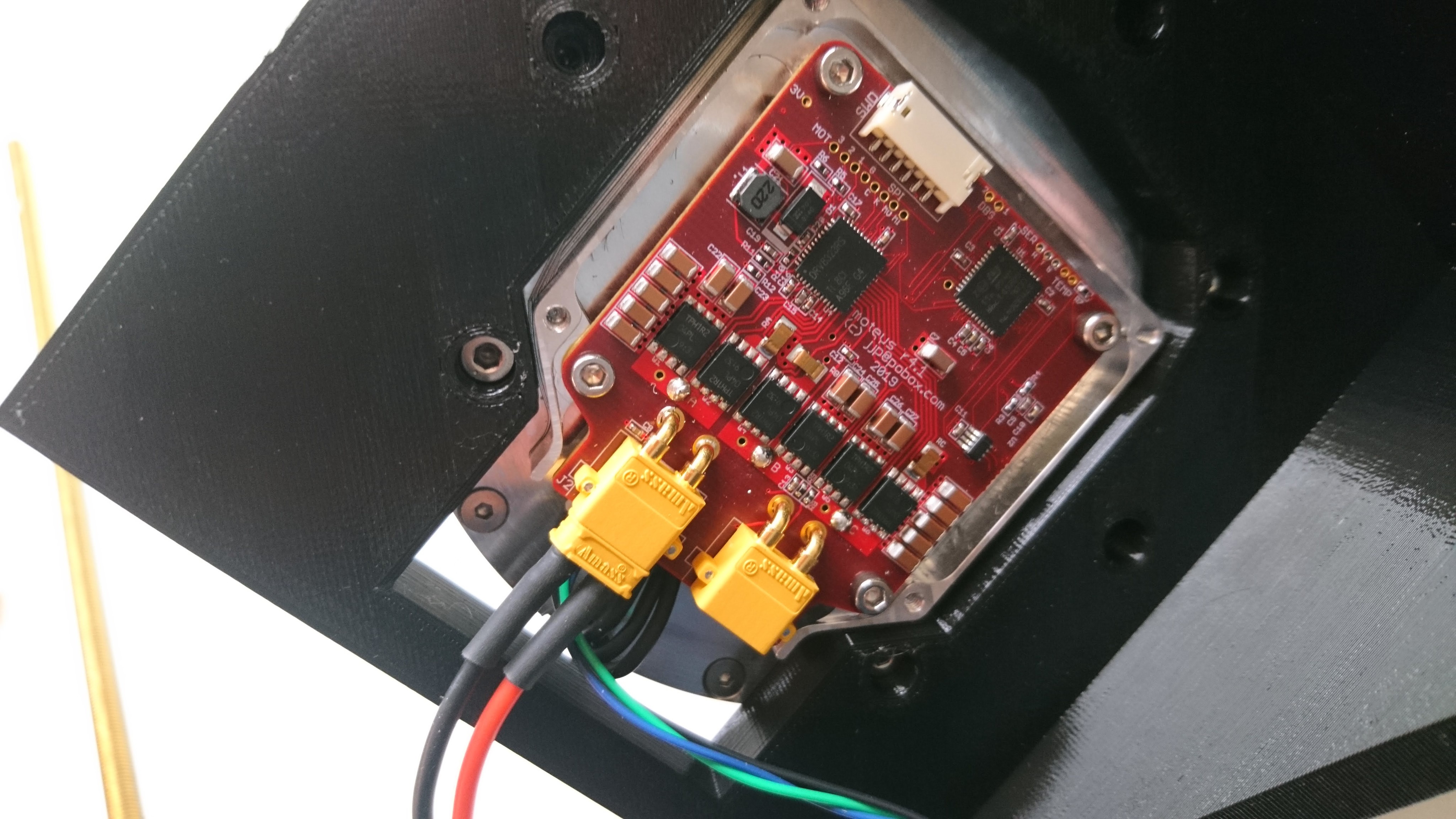
Because my working environment is otherwise too idyllic and peaceful, I’ve been running the new moteus servo mk2 through its paces. All day long. 8 hours a day.
This is the same test I ran to verify the controller, only now I’ve done it several times longer to get a better feel for if there are any weak links. Somewhat surprisingly, the ball doesn’t drop all that often, only once an hour or two.