Spread spectrum integration
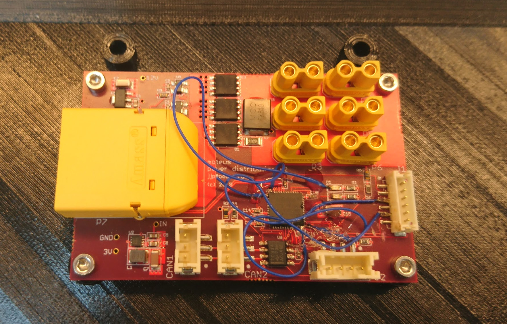
I’ve been developing a new bi-directional spread spectrum radio to command and control the mjbots quad robot. Here I’ll describe my first integration of the protocol into the robot.
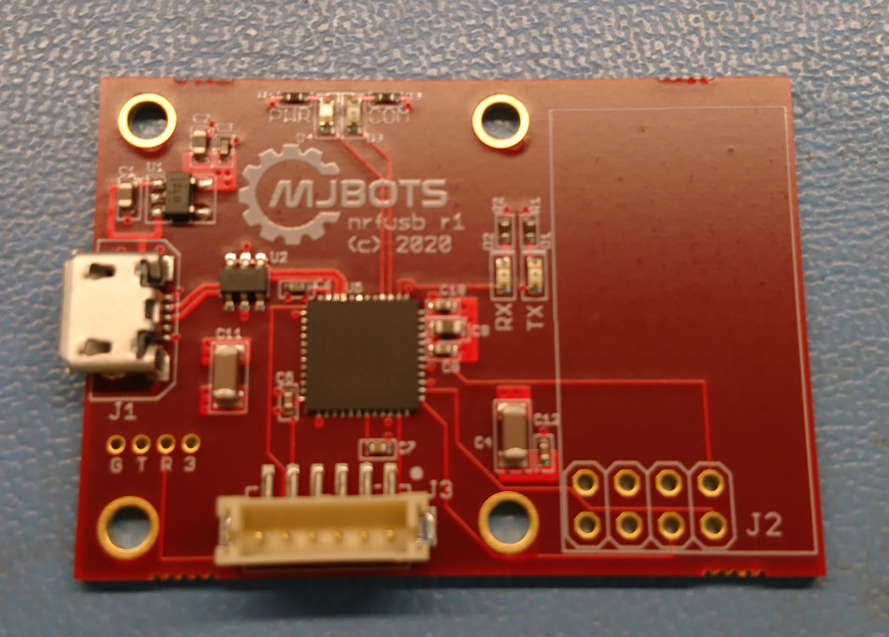
To complete that integration, I took the library I had designed for the nrfusb, and ported it to run on the auxiliary controller of the pi3 hat. This controller also controls the IMU and an auxiliary CAN-FD bus. It is connected to one of the SPI buses on the raspberry pi. Here, it was just a matter of exposing an appropriate SPI protocol that would allow the raspberry pi to receive and transmit packets.