Archives: 2025

Thermal modeling for moteus and motors - a beginning

One of the things I’ve been wanting to understand better for quite a long time is the thermal performance of moteus and motors when used in realistic applications. In many, if not most systems, thermal limits of one or another determine the eventual sizing of controllers and motors and are one of the most important performance factors. I’ve covered this before to a superficial degree in a previous post (customizable pwm rate) but it was far from a general solution. The newly provisioned dynamometer fixture, with its ability to accurately measure input current and power, provided a great opportunity for finally tackling this. This post will describe a bit of the motivation for the work and why you should care.

MR30 and MR60 connectors now at mjbots.com

This post will be short and sweet. https://mjbots.com now stocks mating solder cup MR30 and MR60 connectors:

As their name implies, MR30 are good for 30A peak (15A continous) and MR60 are rated for 60A peak (30A continuous). They have their own built in strain relief attachment, so no heatshrink is necessary during cable construction. Since moteus controllers have no connectors for motor phase wires, these can be used inline if you need to frequently disconnect and reconnect motors. We use them all the time here and figured that you might as well!

Improved dynamometer

Long ago, in a workshop not so far away, I built a dynamometer for characterizing moteus controllers and motors. In the intervening 5 years, we released the moteus-r4.11, moteus-n1, moteus-c1, and now the moteus-x1! For each of these controllers, and the many firmware releases in between, this fixture has still served as a critical part of the validation procedure for new firmware releases and new product releases. However, it was time for a few improvements when tackling the moteus-x1, so here is a brief write up of the new result.

moteus-x1

I’m excited to announce the release of the newest moteus motor controller, the moteus-x1!

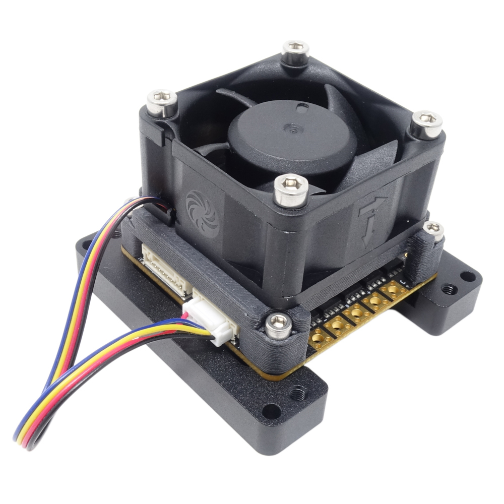
The biggest differences between the moteus-x1 and other moteus controllers is improved output phase current capacity. The x1 is rated for 25A continuous output phase current with no cooling and 60A continuous with fan based cooling. The other big improvement are 12V fan output pads with PWM support. Supporting high power cooling helps the x1 to achieve its higher output current rating.

Improving motor constant calibration in moteus

moteus is able to for many motors automatically determine all the relevant parameters that are necessary for control. That includes phase resistance, phase inductance, torque constant and pole count. The calibration routines have worked pretty well for a wide variety of motors and all the currently available moteus controllers, but when working to expand the supported envelope recently I undertook an effort to make that support even broader, specifically to improve accuracy when measuring resistance and torque constant, and to reduce outliers when measuring inductance.

Representing torque constant as Kv in moteus

One of the characteristic metrics of brushless DC motors is the Kv value, which describes the relationship between the angular velocity of the motor and its back EMF. Somewhat unexpectedly, this constant also completely determines the torque constant of the motor, i.e. the relationship between phase current and mechanical torque output (see this Things In Motion post).

Since the very first release of moteus, this Kv constant has been stored in moteus using somewhat non-intuitive units as motor.v_per_hz. That makes a lot of sense internally, as nearly all math the controller has to do can be natively done with those dimensions. However, as a user visible motor constant, it is completely opaque. Further, as a result of my incremental discovery of the math behind BLDC motors, the constant used by moteus had some additional “fudge” factors baked in that were then backed out through other “fudge” factors in the firmware.

Current mode commutation calibration in moteus

Way back in 2019, I documented the approach moteus has used for encoder commutation calibration ever since. In principle, it commands a fixed voltage that is swept through a range of electrical angles. Assuming the voltage is large enough, this will drag the rotor around with it similar to if the motor was a stepper motor. While that is happening, the commutation encoder reading is recorded over time, so that a mapping can be made between commutation encoder and the electrical angle of the motor. When combined with the old dead time compensation technique, it resulted in relatively sinusoidal current waveforms and thus smooth motion of the rotor and a smooth mapping.

Rethinking dead time compensation in moteus

Way back in 2021, I wrote up a post detailing a method for improving the linearity of the relationship between applied voltage and current for moteus, particularly during the calibration phase. At the time, this did solve a real problem – during calibration, moteus applied a fixed voltage to the phase terminals, swept the electrical angle of that voltage, and hoped that the mechanical angle as sensed with the on-axis sense magnet matched well. However, as a result of some new work, I’ve found that the premise behind that approach was flawed and it needs some re-thinking. This describes what I found, and what’s being done to resolve it going forward.

Moaar power!

Exciting news! All the existing moteus controllers in the world now have an upgraded default maximum power and upgraded rated maximum power as of release 2025-03-27! Depending upon the input voltage and PWM rate, sometimes nearly twice the amount. First, check out the comparison table, then the rationale:

Old default max / rated New default & rated
moteus-r4 340W / 450W 900W <= 30V, 400W >= 38V
moteus-c1 75W / 100W 250W <= 28V, 150W >= 41V
moteus-n1 340W / 1200W 2kW <= 36V, 1kW >= 44V

Background, why a power limit?

moteus brushless motor controllers drive 3 phase PMSM motors, accepting a DC input voltage, and outputting current to each of the 3 phases of the motor. It does so using MOSFET based switching, which alternately connects each phase to either ground, or the DC positive input. As that switching progresses, charge is either drawn, or replenished into, the onboard bulk capacitors.