Thermal modeling for moteus and motors - a beginning
One of the things I’ve been wanting to understand better for quite a long time is the thermal performance of moteus and motors when used in realistic applications. In many, if not most systems, thermal limits of one or another determine the eventual sizing of controllers and motors and are one of the most important performance factors. I’ve covered this before to a superficial degree in a previous post (customizable pwm rate) but it was far from a general solution. The newly provisioned dynamometer fixture, with its ability to accurately measure input current and power, provided a great opportunity for finally tackling this. This post will describe a bit of the motivation for the work and why you should care.
Simple thermal modeling
A thermal model of a system is one that relates the quantities of heat and temperature and how they evolve over time. For any given system, you can imagine it as a black box where heat goes in one side (the thermal load), heat goes out the other side (cooling) and the system itself has a temperature that changes over time. In practical systems, the cooling heat transfer is related to the difference between the system’s temperature and ambient temperature and the warming heat transfer is often either a static quantity or an independent variable that is divorced from the ambient temperature. A given system can also be characterized by it’s “thermal capacity” or its ability to resist temperature change. A device with a higher thermal capacity will increase temperature more slowly for the same heat input.
As a trained electrical engineer, I usually model these with equivalent electrical circuits, and the most common one looks just like this:
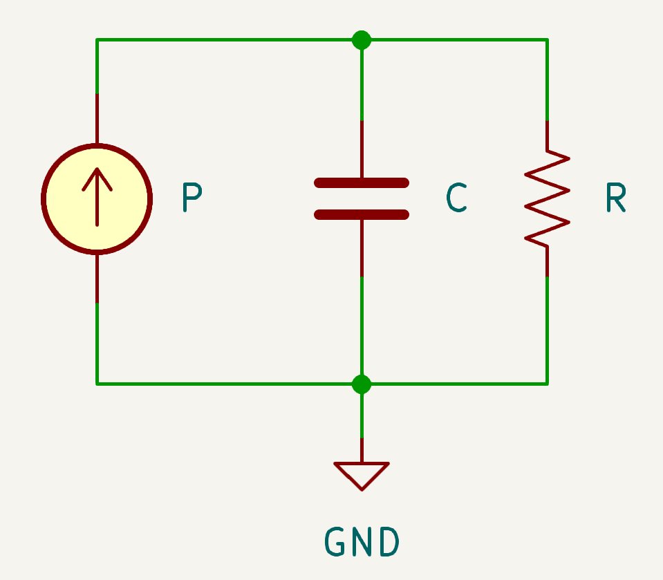
Equivalent electrical model for thermal system
In this model, the constant current source represents the thermal energy entering the system, usually ultimately caused by inefficiencies like electrical resistance. The capacitor represents the thermal capacity of the system. The voltage of the capacitor is the temperature difference between the device and ambient. Finally, the typical cooling function is represented by the resistor. As the temperature/voltage increases, the current through the resistor increases, representing increased cooling thermal energy.
When you need to perform calculations on these quantities, the values you operate on look like this:
- P - input thermal power, usually measured in watts
- R - thermal resistance to ambient, measured in degrees kelvin per watt
- C - thermal capacity, measured in joules per degree kelvin
If you want to find the steady state temperature of a system, i.e. the temperature after an infinite amount of time, you don’t need to know the thermal capacity at all. You can simply divide the thermal power by the thermal resistance.
$$T_{infinity} = {P \over R} + T_{ambient}$$
If the temperature started at ambient, you can determine the temperature at some future point in time in seconds using the following formula:
$$T(t) = PR(1.0 - e^{-t \over {RC}})$$
Controller peak phase current
Now lets talk about the performance parameters we care about, starting with a controller, or PCB that drives a brushless DC motor. The first parameter actually has nothing to do with thermal considerations at all, or at least not directly, and is the peak output phase current. This is the maximum phase current the controller can produce, even if it is for only a very short period of time. Several different considerations go into determining it, but suffice it to say it is a hard limit on the instantaneous current the controller can produce.
Controller continuous phase current
Next, let’s consider the two performance parameters that are so important they are front and center on the main page of https://mjbots.com for each controller: continuous phase current with and without cooling.
With brushless DC motors, the torque produced by the motor before any reducer can be modeled to the zeroth order as linearly related to the phase current applied to its windings (in the Q axis for those who are picky about details). Thus if you need more torque, you have to apply more phase current. Note, the phase current is not the DC input current to the controller. Brushless motor controllers act like step down DC/DC converters. Their input is a high voltage and low current, their output, the phase current, is lower voltage and higher current.
If you are designing a robot or motion system, often you have a rough idea of what torque is required in steady state, or at least on average. You then have to decide how to produce that much torque. The 3 major components you have to select to accomplish that are the motor, reducer and controller, and each should be sized appropriately. Your motor and reducer selection will determine how much phase current the controller has to produce. Generally higher phase current motor controllers are either more expensive, or require more expensive or less desirable cooling solutions.
The reason that motor controllers have a “maximum continuous phase current” is ultimately due to thermal limits. As they provide power to the motor, they generate waste heat, which will increase the temperature of the controller. There are several sources of this waste heat: resistance in the power MOSFETs, current required to drive the gates of the MOSFETs, steady state power required to operate the microcontroller, and inefficiencies in the voltage regulators providing the low voltage busses are the primary contributors.
The maximum current output occurs when the equilibrium temperature reaches the maximum operating temperature of the controller. That’s why moteus boards have two continuous output ratings. One assumes basically no cooling, i.e. a lab environment sitting on a desk. The “w/ thermal management” value assumes that you are applying the maximal documented cooling solution, often a large fan pointed directly at the board, so as to achieve the lowest possible thermal resistance between the controller and the ambient environment.
Controller phase current for X seconds
This value is not specified for moteus controllers, but could be calculated if you know the effective thermal waste heat energy, heat capacity of the board, thermal resistance to ambient, and the maximum operating temperature. For a given time window, this value describes how much current you could emit before reaching the maximum operating temperature. Generally, after reaching it, some period of operating below the continuous current limit is necessary for the controller to actually cool back down again, and in many cases this may be quite a long time. Knowing this value can be useful when an application has high peak load demands relative to the continuous output. A relevant example would be for a legged robot that has to jump or perform dynamic walking motions.
Motor peak current
Next we’ll look at the parameters relevant to a motor. Like for a controller, a motor will have a peak current that can be driven through it, even if for only a very short time. This limit is rarely thermal, but can be because of demagnetization of the magnets or mechanical limits on magnet adhesion or windings. Often, this limit is never specified.
Motor continuous current
When looking at thermal properties of motors, there are different phenomena that result in heat energy being injected into the system. The two biggest in brushless motors are “copper loss” and “iron loss”. The copper loss can be imagined as the resistive heating in the copper windings. It will be proportional to the square of the phase current, is independent of rotation speed, and can be imagined as ohmic losses. Iron loss results from residual eddy currents in the iron stator induced by the rotating magnets as they pass by. It is primarily linear with respect to the motor’s velocity and independent of the torque that is being applied. These two values together determine how much thermal heating energy is applied to the motor at any given operating point, although for many practical applications, the copper losses are much higher than the iron losses and thus the iron losses can often be largely ignored.
Inexpensive motors will sometimes specify only a single current limit or “continuous current”, which will be equivalent to the moteus definition of current “with thermal management”. That means that this current could be maintained with maximal specified cooling while at the maximum operating temperature. For motors that were originally intended for drone applications, “maximal specified cooling”, could mean a large fan, e.g. a propeller, blowing air directly through the copper windings.
Motor current for X seconds
It is rare for a motor manufacturer to specify the phase current that can be achieved for time periods smaller than infinity, but it can be a valuable metric for all the same reasonse as it is a valuable metric for moteus controllers. When an application requires high non-uniform torque production, then it can be the defining metric.
Coda
The parameters described here so far are largely the thermal ones. There are times when other metrics end up being the determining factor. Some possibilities are:
- Maximum speed: The motor’s maximum speed will be determined by its physical construction. The overall system’s maximum speed will be determined by the system voltage, the motor’s Kv value and the modulation depth of the controller. If the maximum speed is insufficient, then either a higher system bus voltage is required, or a motor with a higher Kv winding is required (which may require higher phase currents for the same torque).
- System voltage: In some systems, the DC bus is pre-defined, thus whatever controller you select must support operation across the range of input voltages.
- Mass and size: If you are limited to be within a given mass or size envelope, then clearly the controller and motor must fit. Even if not a hard requirement, they are often useful performance metrics.
There are also some notable “non-metrics” motor parameters that often confuse people.
- Rated motor voltage: Many motors have a “rated voltage”. In practice this is not a constraint at all, but is often just a “recommended system voltage”. The actual maximum voltage for a motor is usually determined by the breakdown voltage of the copper winding’s enamel, which is usually quite high. It can also be a proxy for “maximum speed”, as in the speed you can achieve at the rated voltage may be the maximum mechanical speed that the motor is capable of. In any event, in nearly all cases you can select the system voltage without regard to the rated voltage.
- Continuous power: This metric, if present, is not usually useful in robotics applications. Instead, it is intended to apply to thrust generating propeller applications. This continuous power is specified when operating at a continuous torque at a continuous, relatively high speed.
- Kv: The Kv value is important, but it does not determine a motor’s thermal performance. For a given motor design and total amount of copper winding wire, you can change the Kv rating by using more or fewer wires in parallel. Higher Kv ratings will require more current to generate the same torque and be capable of a higher speed for a given system voltage. Lower Kv ratings will require less current to generate the same torque but have a lower maximum speed for a given system voltage. Importantly though, for a given speed and torque, both the copper and iron losses will be identical no matter the Kv value. Thus the metric is more about matching the motor to your controller and system voltage than it is about motor selection.