Improved dynamometer
Long ago, in a workshop not so far away, I built a dynamometer for characterizing moteus controllers and motors. In the intervening 5 years, we released the moteus-r4.11, moteus-n1, moteus-c1, and now the moteus-x1! For each of these controllers, and the many firmware releases in between, this fixture has still served as a critical part of the validation procedure for new firmware releases and new product releases. However, it was time for a few improvements when tackling the moteus-x1, so here is a brief write up of the new result.
To begin, there were a few areas I was looking to improve:
-
Reproducibility: The original used a random fixture plate from ebay, with a bolt pattern that could not be sourced even a few months after the initial was built.
-
Torque accuracy: The old torque transducer was severely oversized for the loads involved, resulting in rough accuracy of worse than 0.2Nm.
-
Input power/current: There was no way to measure the input power or current, and thus no way to measure the overall efficiency of a motor and controller pair.
Let’s tackle each of these in turn:
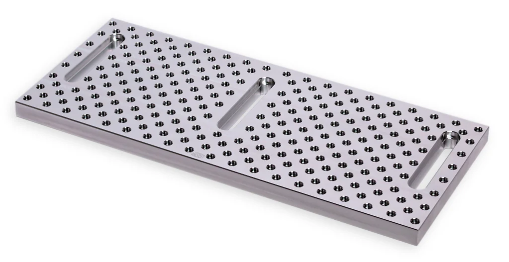
For the fixture plate, the new version uses one from Sanders Machine Works, their Universal Aluminum Fixture Tooling plate, the 14" M6 version. This is a stocked product that is likely to remain available for some time and as a bonus, can be obtained in a 20" version if a longer stackup is needed in the future.
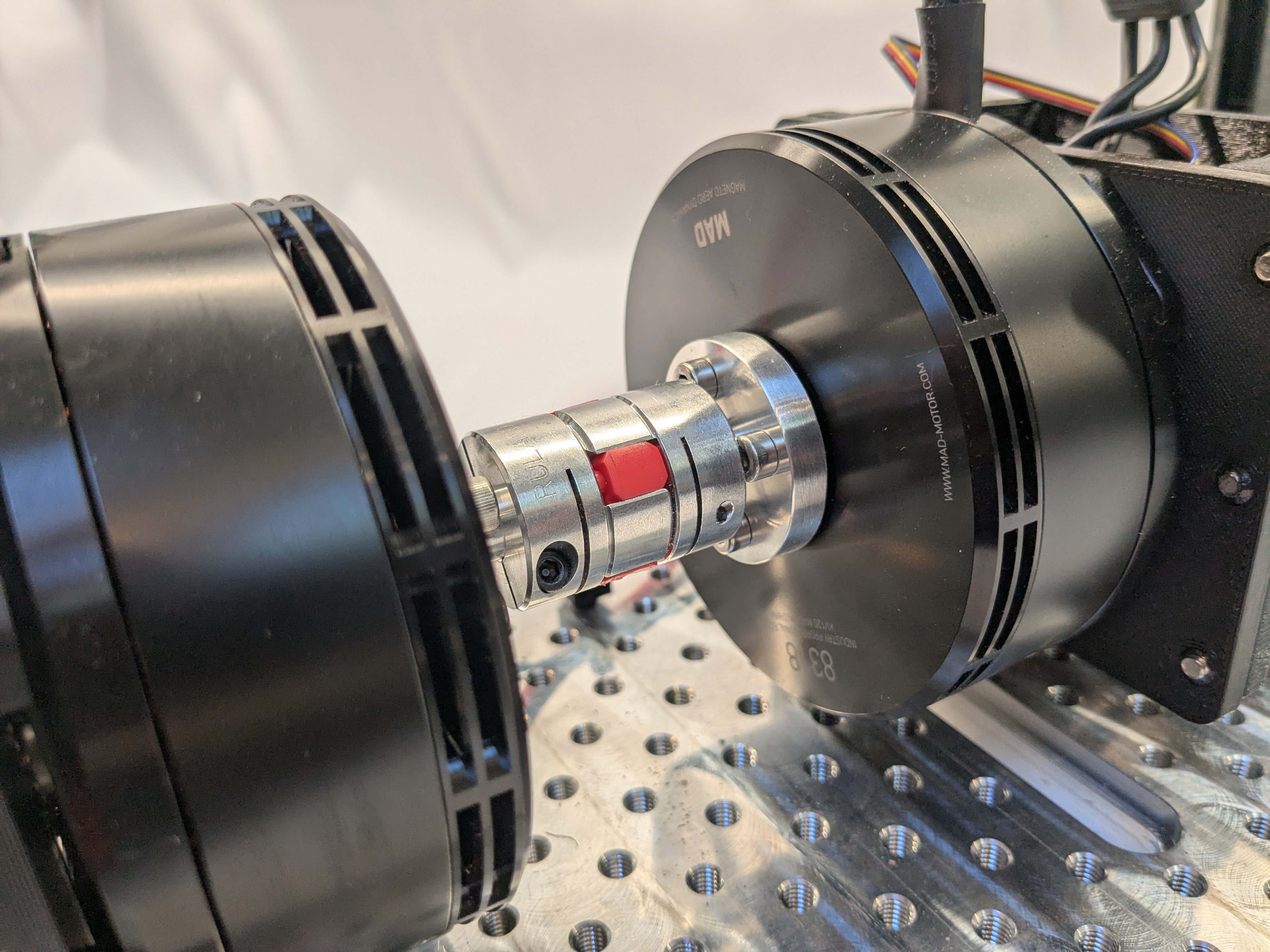
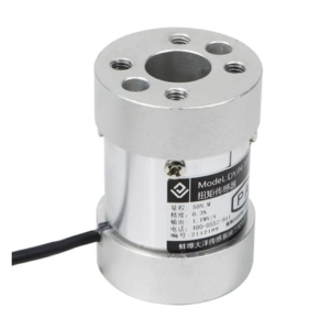
To improve the torque accuracy, I switched to a smaller torque transducer, this time from aliexpress. With the current 2025 tariff situation, their availability has dropped in and out, but as of the writing now, they were procurable for around $100 USD each:
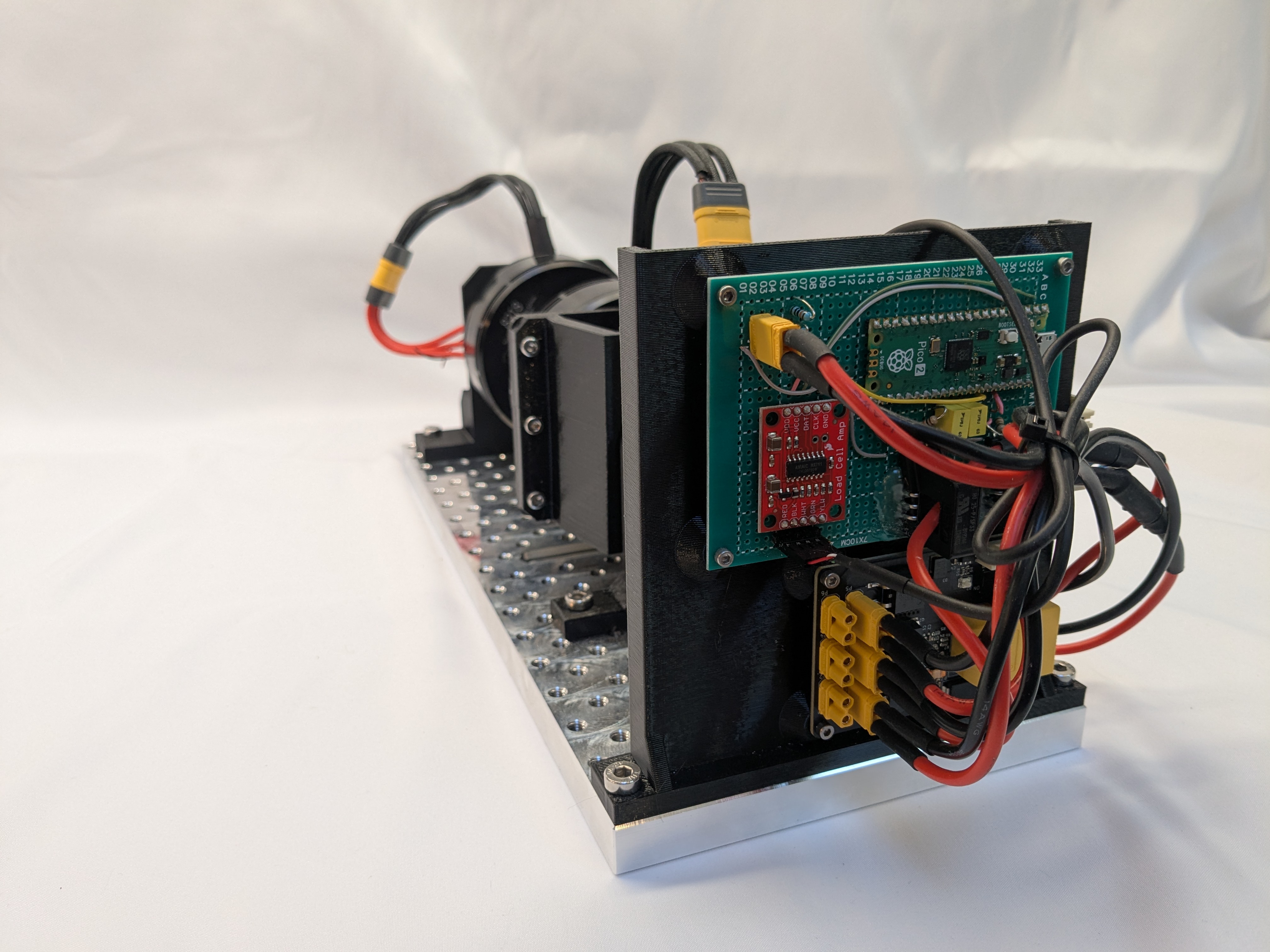
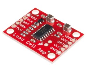
That transducer then connects to a SparkFun HX711 breakout board to produce an analog output signal.
To measure the input current, I first built one solution which works, albeit poorly. In that setup, both the load and device under test controller are powered from a mjpower-ss, but their power cables are each routed through a separate hall effect current sensor. Those hall effect current sensors each output a ratiometric analog signal that corresponds to the current going to and from each controller.
That setup generates at least 4 analog voltages to sample, the 2 input currents, the torque transducer output, and the input voltage. In my prototype here, I decided to experiment with something new and use a Raspberry Pi Pico 2. It was cheap, had a small form factor, and is likely to be available for a long time. I made a simple MicroPython program to sample all of the sensors and emit the results as JSON over the serial port. This works fine, although I hadn’t really counted on the poor ADC performance of the RP2350 used in the Pico 2. I didn’t investigate too closely, but at least on the pico2, at best I was getting 8 bits of accuracy from the ADC and probably less than that.
Thus I fell back on a quick and dirty hack, and for anything where current sense accuracy mattered, I just powered the device under test from my Chroma 62006P-100-25 supply, which can be queried for relatively accurate current and voltage readings over USB, at least down to the milliamp for current and 3 decimals for voltage.
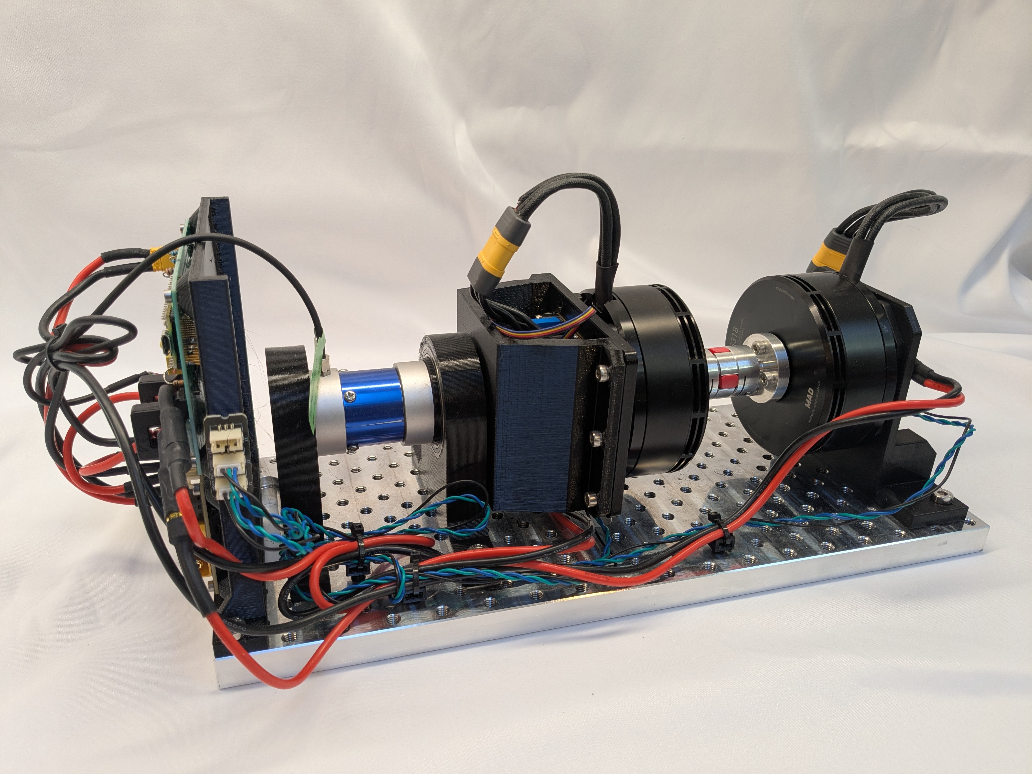
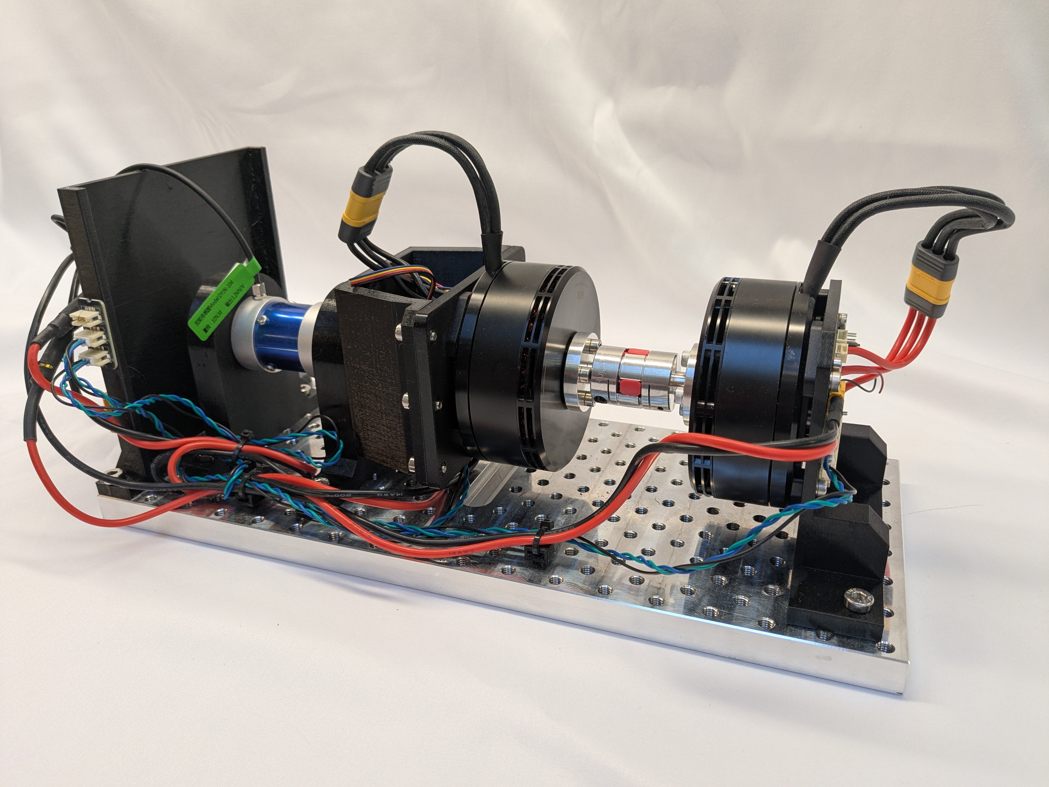
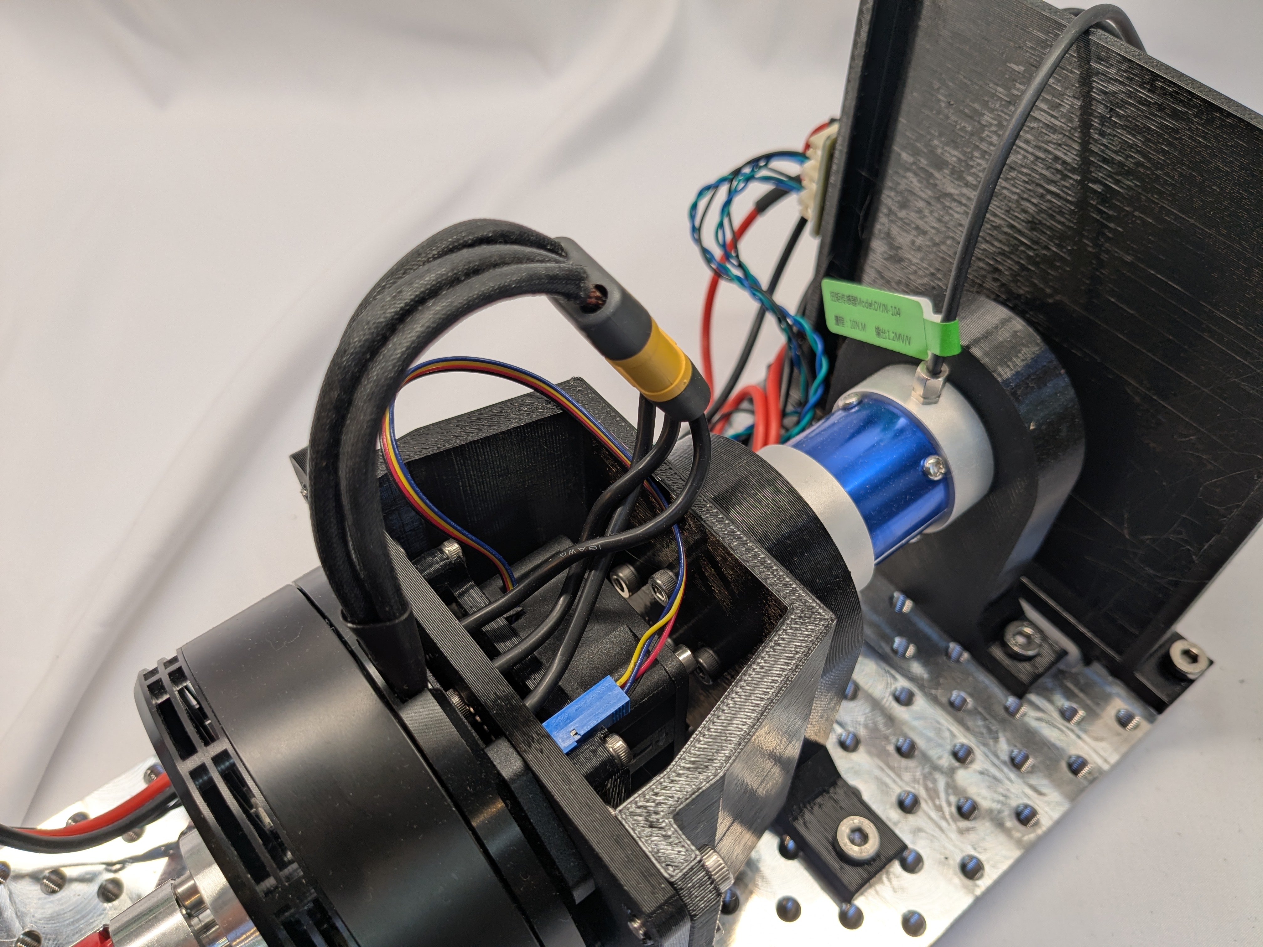
The end result looks like this: