Improving motor constant calibration in moteus
moteus is able to for many motors automatically determine all the relevant parameters that are necessary for control. That includes phase resistance, phase inductance, torque constant and pole count. The calibration routines have worked pretty well for a wide variety of motors and all the currently available moteus controllers, but when working to expand the supported envelope recently I undertook an effort to make that support even broader, specifically to improve accuracy when measuring resistance and torque constant, and to reduce outliers when measuring inductance.
Resistance improvements
The method moteus uses to calibrate phase resistance is to command a progressively increasing series of fixed PWM values and measure the average current that results. If one assumes that a fixed PWM value corresponds to a fixed average voltage applied to the phase windings, then this would result in a great estimate. However, as recently covered in the elimination of dead-time compensation, there are definitely non-linear effects that make this not work as well, especially in the region near 0 current where we would like to be measuring resistance (so as to not get the motor too hot during calibration).
The old algorithm would first geometrically ramp up voltage/PWM duty cycle until the desired motor power was achieved. Then it would sample the current at a range of fixed duty cycles corresponding between 50% and 100% of this calibration power determined duty cycle.
The new algorithm instead operates in a single pass and performs a simple two point fit between the highest current sampled that is less than 60% of the maximum, and the maximum value. By selecting the sample points based off of current instead of voltage, it is much more likely to be outside the non-linear region near 0 current. A least squares fit was in practice only more sensitive to noise than the 2 point version.
Overall this change doesn’t result in drastic improvements, but does improve the consistency of results across all different board types. The one outlier is that it is unable to compensate fully for the increased non-linearity from deadband compensation removal when the moteus-c1 is used with very low phase resistance motors. Given that the moteus-c1 isn’t generally a good fit for those motors anyways, this isn’t a very large problem.
Inductance
The inductance measured by moteus is not all that critical currently, it is currently only used along with resistance to set the current control bandwidth (see Auto-tuning current control loops). However, most users would probably expect the resulting selected current control bandwidth to be at least within a factor of 2 of the actual result, which was not always the case with the existing algorithm.
To recap, moteus measures inductance by applying a square wave voltage, and then integrating how quickly the current increases during the positive part of the square wave and how much it decreases during the negative part. To date, a single frequency of square wave was applied, centered around 0V.
The biggest problem this technique had was with high resistance, low inductance motors. It also started to give very inaccurate results when deadtime compensation was removed, as the applied voltage waveform was right in the middle of the biggest area of non-linearity when the motor is at zero speed.
The improvements here were twofold. First, instead of using a single test square wave frequency, moteus_tool now steps through a range of frequencies, selecting the one which results in the highest current / lowest inductance. Second, the square wave is no longer centered around 0 voltage, but around a non-zero offset which hopefully results in an average current that is well outside the non-linear range.
These changes improve the consistency of measurement across all motor types. Specifically for low inductance high resistance motors, the previous results were off by an order of magnitude. While not perfect, the new approach gets within a factor of 2x instead of 10x on those motors.
Torque constant
The Kv value is perhaps the most important constant that moteus measures, as it directly corresponds to the torque constant of the motor. This constant is the relationship between voltage and speed. Being accurate here allows moteus to accurately report applied torques, precisely limit torque, and means that the PID control constants are normalized across devices.
The Kv detection algorithm changed in a similar manner to the resistance calibration algorithm with some additional heuristics. Previously it operated by geometrically increasing the Q axis applied voltage until the motor spun at a given speed, 10Hz by default. Then equally sampled Q axis voltages between 0 and the 10Hz one were sampled, with a linear regression used to determine the final Kv value.
The biggest problem with this approach was with motors that had significant stiction, i.e. ones that require a moderate Q axis voltage in order to move at all. For those motors, sometimes only a single data point would move at all, and sometimes 0 data points if the 10Hz spin got lucky the first time and unlucky the second time.
Now, during the initial geometric Q axis phase, the procedure continues increasing the voltage until the measured speed is at least twice the first non-zero measured speed. Then, when sweeping through speeds after to collect the sample data, only data points that move above 45% of the maximum speed are used. Further, the result of this procedure was calibrated using an oscilloscope and torque transducer across a variety of motors and controllers.
The new approach improves the reliability of the measurement quite a bit, especially with high stiction motors. The consistency is improved as well, and the calibration results in measurements that are nearly always within 25% of actual, and often within 5% of actual.
Validation
Before I started working on these improvements, I measured the ground truth constants for a set of different motors that covered a pretty good spread of the types of hobby-ish motors people have been using with moteus. The resistance was measured by applying a constant current using a lab supply and measuring the voltage. This gives pretty accurate results even for motors with phase resistance measured in 10s of milliohms. The inductance was measured with an LCR meter connected across two phases. The Kv constant was measured by spinning the motor with a separate moteus/motor pair, and using an oscilloscope to measure the peak to peak voltage at a few different speeds. The resulting lineup:
| Motor | Line to center R | Line to center L | Kv | Mass | Notes |
|---|---|---|---|---|---|
| mj5208 | 0.047 | 28.6e-6 | 304 | 193g | moteus devkit motor |
| MAD 8318 | 0.015 | 9.75e-6 | 115 | 646g | Relatively low resistance and inductance |
| GL80 | 0.257 | 140.0e-6 | 53.5 | 324g | Moderate resistance and inductance |
| HT1105 | 6.435 | 298.5e-6 | 1180 | 7.2g | Very small, significant stiction, low inductance to resistance ratio |
| GBM5208 | 7.545 | 2254.5e-6 | 25.5 | 190g | Gimbal wound low current motor similar in size to mj5208 |
Using a lab supply set to 24V, for each of these motors, I ran the full calibration sequence 4 times with each of a moteus-r4.11, moteus-n1, moteus-c1, and an unreleased board. This experiment was repeated for three configurations:
-
The last release of firmware and tools, 2024-11-04 (old / old)
-
The last release of firmware, but upgraded tools (new / old)
-
The current release of firmware and tools, 2025-03-27 (new / new)
The hope would be that the new tools would give improved results for both old and new firmwares, accepting that the best results would only be available if both were the most recent.
Given that, here is the super-chart showing the results from all 5 motors for resistance, inductance and Kv across 3 (and a 4th in the new / new test) controllers.
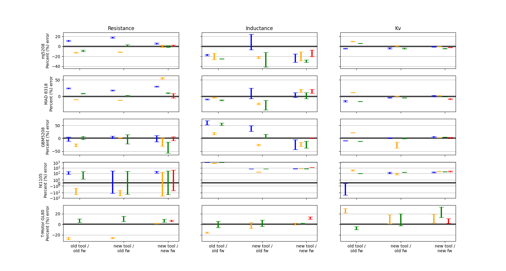
And the statistics for the old/old and new/new configurations are below.
| Old Average Error | Old Stddev / Worst Error | New Average Error | New Stddev / Worst Error | |
|---|---|---|---|---|
| Resistance (excluding moteus-c1 / MAD8318) | 32% | 51% / 133% | 2% | 18% / 53% |
| Inductance (excluding HT1105) | 1% | 28% / 81% | 7% | 17% / 39% |
| Kv | 3% | 16% / 42% | 7% | 10% / 40% |
Caveats and take aways:
-
In the chart, the HT1105 is measured logarithmically, since the original inductance measurements were more than 1000% off (although even the improved readings are still ~70% off.
-
Consistency of measurements across boards is definitely improved across all motor types.
-
The GL80 tests were performed using an external MA600 with diametric ring magnet using only BCT tuning and no non-linear compensation. This likely accounts for some of the error in the Kv measurement.
-
The moteus-c1 has ~55% resistance error on the MAD 8318, which is actually worse than before due to the removed deadtime compensation.