Rethinking dead time compensation in moteus
Way back in 2021, I wrote up a post detailing a method for improving the linearity of the relationship between applied voltage and current for moteus, particularly during the calibration phase. At the time, this did solve a real problem – during calibration, moteus applied a fixed voltage to the phase terminals, swept the electrical angle of that voltage, and hoped that the mechanical angle as sensed with the on-axis sense magnet matched well. However, as a result of some new work, I’ve found that the premise behind that approach was flawed and it needs some re-thinking. This describes what I found, and what’s being done to resolve it going forward.
Background
First off, all the data and modeling captured during the experimentation phase 4 years ago still holds. The non-linearity between applied PWM duty cycle and measured current definitely exists and follows the multi-dimensional pattern as shown in the plots there.
What that data misses, is the effect of back-emf on the observed non-linearity. All of the data collected during those experiments was at 0 speed, so there was no back-emf observed from the motor. My assumption at the time was that the non-linearities would be related to the PWM duty cycle and would be centered around a relative duty cycle of 0, regardless of how much back-emf was present.
Updating my assumptions
While working on something new (and bigger!), I spent some time trying to find a more accurate model of this dead time so as to fit alternate drive circuits. After having gotten tired of devising increasingly detailed lab experiments, I decided to attempt to model the drive topology in SPICE and see how close it could get. This turned out to be quite an exercise in frustration!
To start with, I modeled the DRV83x3 gate driver as a set of time controlled current sources:
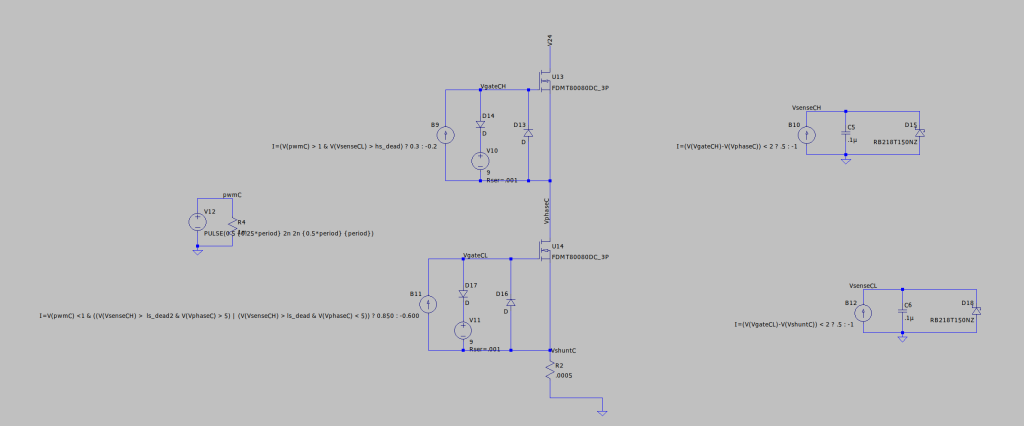
Each half of the H bridge included a current source that would either charge or discharge the FET using a current that matched the configured drive strength. Clamping voltage sources and diodes ensured that the gate drive voltage matched what the actual device provided. Much of the non-linearity was directly related to the behavior of the DRV83x3 gate driver, particularly its shoot through protection. To model that, a separate “sense” circuit was used which charged a capacitor to time how long the opposing gate had been turned off.
The biggest problem here was finding appropriate MOSFET models. ngspice, which is integrated into KiCAD, has some selection, but basically no modern power MOSFETs are included in its library. Most vendors do provide simulation models, but typically only for one of the major proprietary SPICE solvers and usually in encrypted form. I ended up using LTSpice, mostly because it was free, but also because it was reported to run under Wine relatively well. I hoped to use that to accomplish broad parameter sweeps programmatically across many cores.
Unfortunately, the above circuit turned out to be highly unstable when simulated on LTSpice, depending upon the simulated parameters. Usually I could get it to work, but doing so often required configuring a very low maximum time step which would make simulations take a very long time, particularly near 0 output current when dead time effects were most pronounced.
Gripes about LTSpice
I would have course preferred to use ngspice for this effort, but since I could not get a FET model that reproduced the effects I cared about, LTSpice was what I was stuck with. Here’s a list of some of the gripes I had after working with it:
-
Parallelism: Yay, in that it can run on multiple cores. However, big boo that it uses some heuristic to determine how many cores to use that seems both a) largely random when run under Wine, and b) drastically underutilizes machines with large numbers of CPUs.
-
Instability: The “time step too small” was the bane of my existence during this effort. This may be an artifact of trying to model a highly non-linear system, but getting usable results required a fine balance of selecting the maximum time step. If it was too large, errors resulted. If it was too small, a single simulation run could take hours to complete.
-
Scriptability: You might think that you could use LTSpice’s built in scripting methods to sweep across the parameter space. However, if any step in the simulation triggered a “time step too small” error (see above), the whole run would be aborted without printing the results!
-
User Interface: Well, I guess you have to expect the UI to be crufty for a free EDA tool that has been around as long as LTSpice, but boy, just driving the mouse with it was painful.
-
Broken release: I first went and downloaded the most recent release (24.1.something), which turned out to be nearly completely broken in its ability to not fail during simulations. Fortunately, I was able to locate a working version 24.0.12.
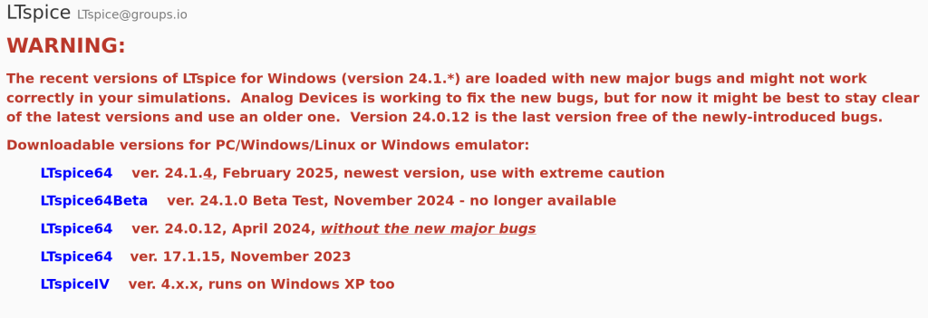
Snapshot of https://groups.io/g/LTspice
Modeling results
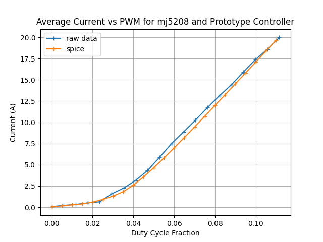
Despite the pain, with sufficient dedication I was able to tune my DRV83x3 simulation and the motor models to get results that closely aligned with my observed results for a range of motor parameters and supply voltages.
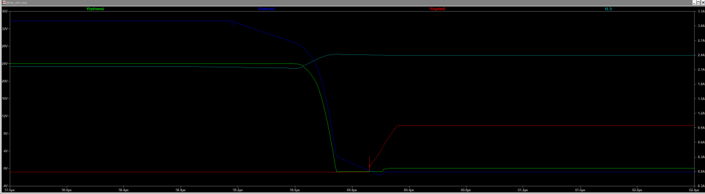
LTSpice simulated gate waveforms for a single phase
The surprise came when I ran the simulation assuming that the motor was spinning and was producing back EMF. This was hard for me to capture clean traces of on the oscilloscope, but it was trivial to capture in LTSpice. Once I did that, I had my big a-ha moment. The non-linearity was not in fact around 0 PWM duty cycle, but instead around 0 current!
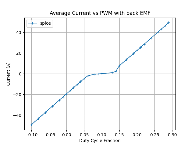
That means that while the earlier moteus compensation technique would improve linearity when a motor was stationary, it would strictly degrade linearity at any other motor speed. It also had the effect of increasing audible noise near 0 speed, so this meant that it had some problems at basically any speed!
Future directions
At this point, I decided to just scrap the entire compensation framework. Having it gone wasn’t the end of the world… nearly all moteus control operates in current controlled mode, where the PWM duty cycle is modulated to converge onto a desired phase current. The only thing the compensation was helping with was 0 speed calibration, for which I had some alternate approaches in mind. For basically every other use case it was just increasing audible noise and decreasing the tracking performance of the current controller.