PWM output with moteus
Here’s a bit more in-depth discussion of a yet another new feature from moteus firmware release 2024-10-29: pulse width modulated output on auxiliary ports.
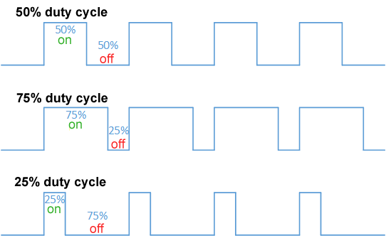
A pulse width modulated signal is a logic level signal of a fixed frequency, where the duty cycle, or width of the pulse, is changed or modulated to communicate a scalar value. Obligatory Wikipedia diagram below:
The new feature does what it claims to do, in that a subset of auxiliary pins can now be configured to output a PWM signal. If so configured, the duty cycle can be controlled using either the diagnostic or register protocol.
Hardware support
First, the only pins which are capable of PWM output are those which are capable of hardware quadrature input. The reason being, is that those are the pins which are connected to appropriate timer hardware on the moteus’s STM32G4 microcontroller. If you look at the pin capability table in the reference manual:
You’ll see that the possible pins are:
moteus-n1/c1: AUX1: B/C/D/Emoteus-n1/c1: AUX2: C/D
Note that for the moteus-c1 on AUX1, only pins D and E are available, and only on an unpopulated pad, not a physical connector. This is unlike the moteus-n1, which has a JST GH8 receptacle for AUX1. Also note that AUX1 B/C are unavailable if the onboard magnetic encoder is being used.
Sadly, the moteus-r4 doesn’t make the cut and has no pins that are capable.
Software configuration
The only mandatory configuration to enable PWM output is to configure the appropriate type for that pin. The necessary value is “pwm_out” or value 17.
aux2.pins.2.mode = 17 # Set AUX2 pin C to be PWM output
Additionally, the period of all PWM output signals for the given port can be configured using:
aux2.pwm_period_us = 1000
Where 1000 us (1kHz) is the default.
Usage
Once you have a pin configured, you can change the output duty cycle in a few ways. First, you can use the diagnostic protocol from tview or python:
aux2 pwm 2 0.5
The above command will drive pin 2 (C) on AUX2 to a duty cycle of 0.5, or 50%.
Register mode commands are available in registers 0x076 through 0x07f: https://github.com/mjbots/moteus/blob/main/docs/reference.md#0x0760x07a—aux1-pwm-outputs
Those register mode commands can be accessed from either the python or C++ library as well. Unfortunately, the pin numbers for the python and C++ API are numbered starting from 1, and not zero as in the configurable values. A short example in python:
c = moteus.Controller()await c.set_aux_pwm(aux2_pwm3=0.5) # set pin C to 50% duty cycle
And one in C++:
mjbots::moteus::Controller c;mjbots::moteus::AuxPwmWrite::Command pwm_cmd;pwm_cmd.aux2_pwm3 = 0.5;c.SetAuxPwmWrite(pwm_cmd);
Applications
The most direct use for this functionality is control of PWM enabled fans. Given that moteus controllers do generate a fair amount of waste heat, a fan is one of the most effective ways of getting the maximum continuous torque from a given device. However, having a fan run continuously can be both noisy and consume more power than is necessary. Using a PWM controlled fan allows it to be disabled or operate at a slow speed when thermal stress is low. The 5V output of moteus-n1 and moteus-c1 are both sufficient to drive many 5V PWM fans, like these from Noctua:
Another potential application is control of RC servos, which typically use a 50Hz - 200Hz frequency PWM signal to control desired position. This does require suitable power system design, as the 5V/100mA output from moteus is unlikely to be sufficient to drive any but the smallest servos, and few servos have overlapping DC input ranges with a moteus controller.
Finally, with an appropriate low-pass filter installed at the output pin, the PWM output can be used to emit an analog output signal value to drive an arbitrary mechanism or circuit that requires an analog input.
Example
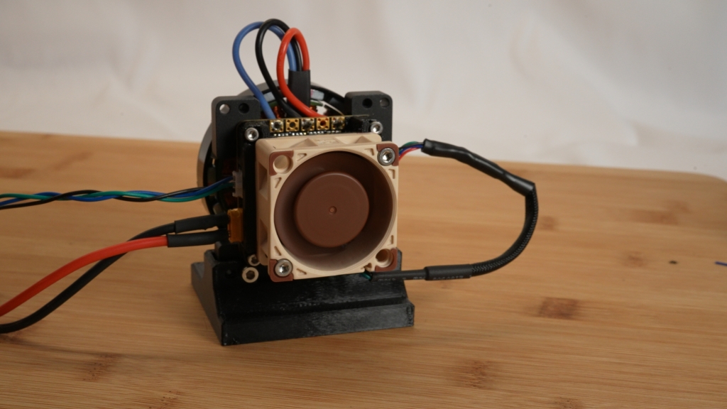
To demonstrate this, I put together a simple example with the NF-A4x20 fan attached to a moteus-n1 developer kit. This simple 3D printed bracket mounts over the n1, and has holes for M3 bolts to thread directly into the plastic to mount the fan. It is intended to be printed at 100% infill with build plate supports, mine was with a 0.6mm nozzle on a Prusa MK3S.
And here is a shot of it assembled:
Finally, here’s a short video showing the fan in operation: