Optimizing moteus command rate
Probably one of the most frequently asked questions in the mjbots Discord is “how fast can I send new commands to moteus”, or “how fast can I read the status from moteus”. That may be because you want to perform torque based control in your application and require high bandwidth, or just because you have a high torque to inertia ratio system that reacts on very short time-scales. No matter the reason, the principles that control the maximum rate you can send updates are the same.
Theory
In a typical application, the host will run a control cycle to determine, given its current estimates of the world, what new commands should be sent. It then needs to send those commands to the servo drives and retrieve the current status of each. The moteus CAN-FD protocol is a query-response one, which means moteus will only send any data in response to a query, although those queries can be included along with command data. Many things have to happen for this to complete!
-
The host application needs to format the CAN-FD message
-
The host application may need to use the operating system to enqueue the message
-
That message needs to be sent over some host bus to a CAN-FD controller, using something like PCIe, SPI, or USB
-
That host controller needs to clock the message out over the CAN-FD bus
-
moteus has to parse the message
-
moteus has to formulate a response
-
The moteus CAN-FD controller has to clock out a response over the CAN-FD bus
-
The host CAN-FD controller needs to process the frame and send it over the PCIe or SPI bus back to the host CPU
-
The host CPU operating system may need to return the message to the host application
-
The host CPU needs to parse the response
When multiple devices are on the same bus, some of these steps can occur in parallel, for instance while the host CAN-FD controller is clocking out one message, it can be receiving another from the host CPU over a SPI bus. Similarly, while one moteus is parsing a message or formulating a response, the host CAN-FD controller can be clocking out a command/query to a different device.
The CAN-FD protocol that moteus uses by default sends most data at 5Mbps, with a header at 1Mbps. However, when the electrical performance of a CAN-FD bus is poor, because there are long links, untwisted pairs, sub-optimal termination, or a number of other reasons, 5Mbps may not be reliable and the designer will need to switch to using only 1Mbps for both the header and data. BRS or bit-rate-switch is the option that enables 5Mbps operation, so disabling BRS results in all frame bits being sent at the slower 1Mbps. Thus as you increase the number of devices on a bus you can get a double effect. At some point, the performance of the bus gets bad enough that you have to turn off BRS and you have an even slower update rate overall.
Note that this list does not actually include your application deciding what the control values should be! For many applications this can take a significant amount of time. For instance, in the quad A1, about half the time is dedicated to running the application control, and half the time is spent sending that data to the servos and getting their responses.
Experiments
To illustrate this, I used the bandwidth_test.cc example from the moteus C++ examples to measure the achievable update rate for a number of different configurations with 1 to 6 devices on the same bus. The three configuration options I used were:
fdcanusb vs pi3hat: The fdcanusb / mjcanfd-usb-1x operates over a USB host bus and is primarily intended for development and diagnostics. It is small, cheap, and is not expected to be necessarily fast. The mjbots pi3hat is a Raspberry Pi 3/4 shield that provides 5 independent CAN-FD busses (and an IMU with attitude reference system). Those are interfaced to the Raspberry Pi over 2 different SPI channels. It is intended for high rate control of many devices across many busses.
BRS ON vs BRS OFF: This is straightforward - for some experiments BRS was enabled, resulting in data being sent over the CAN-FD bus at 5Mbps whereas for others, it was disabled, resulting in all data being sent over the CAN-FD bus at 1Mbps. Notably this does not affect all the non-bus related time involved in a cycle, like application parsing, host bus transmission, or moteus response latency.
Message Resolution: The moteus protocol permits data to be sent and received in a variety of resolutions, depending upon the application’s need for resolution and message speed and also permits different subsets of command and response data. The “defaults” configuration uses the default set of registers and resolutions implemented by the moteus C++ library. That is a position and velocity command as 32 bit floating point values, and 32 bit floating point responses for position, velocity, and torque, and int8 responses for voltage, temperature and fault. The “int16” version uses int16 for everything that the defaults used 32 bit floats for.
And here are the results. The top plots use fdcansb, the bottom use pi3hat. The left plots use BRS and the right plots use BRS disabled. The y axis is achieved update rate in Hz and the x axis is number of controllers on the bus.
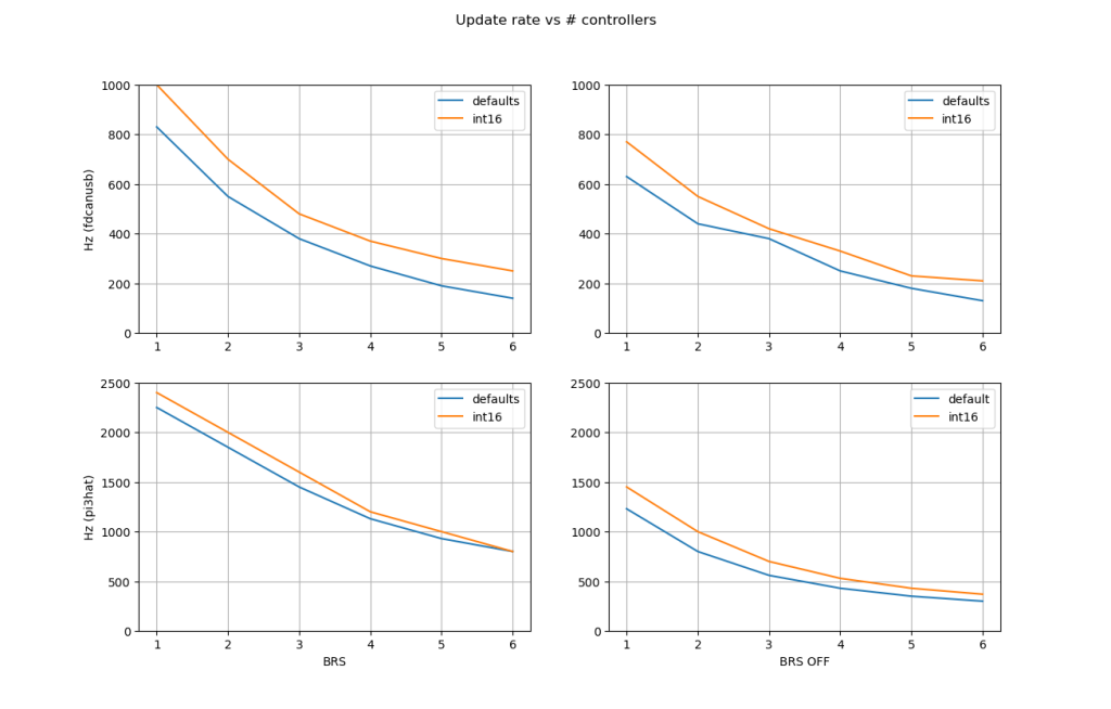
By default, a single moteus with a fdcanusb can achieve ~800Hz, whereas a single moteus with a pi3hat yields around 2200Hz. Those rates drop with the number of controllers and with BRS turned off. Using the lower resolution int16 encoding helps some, by up to 20% in the overall rate depending upon the specific scenario. Remember that your application needs time to do its job as well. That may mean derating these values by 2x or more for any given end use.
Designing a system
First, most applications don’t need to use a fast update rate. If you use the built-in moteus limited acceleration and velocity trajectories, many applications work just find at an update rate of 10-100Hz, which is achievable in nearly all situations even for a large number of servos on the same bus.
If the update rate does matter, then you need to decide upon a minimum set of registers you need to command and query. To start with, it probably makes sense to leave them all at 32 bit floating point resolution.
Second, you should consider splitting devices among multiple CAN-FD busses. With more than one independent CAN-FD bus, nearly all of the steps mentioned above can be performed in parallel.
The next thing to look at is the host adapter. Using a non-USB adapter will give the best results, which for a Raspberry Pi could be the pi3hat, or for another SBC (single board computer) it could be a PEAK m.2 CAN-FD adapter for example.
Once the above is done, you can consider decreasing the resolution of one or more of the command or query registers. This may reduce the size of the CAN frames involved, reducing the time each message spends clocking out onto the CAN-FD bus. https://github.com/mjbots/moteus/blob/main/docs/reference.md#a2a-mappings
In some cases, the time it takes moteus to process and formulate a response can be a significant factor. This would most often occur if multiple encoders are configured and there a small number of devices on the bus. In that case, you can improve the moteus response latency by lowering the PWM rate from the default of 30kHz (the current minimum possible is 15kHz). All control calculations in moteus are performed at the PWM rate, leaving the remainder of the CPU for things like processing and responding to CAN messages. By decreasing the number of control updates per unit time, moteus will finish responding to CAN-FD messages more quickly.