Archives: 2021

Next-gen power_dist (part 2)

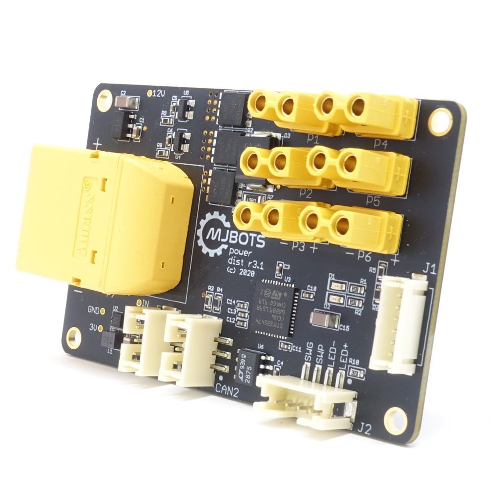
Last time I covered the limitations of the power_dist r3.1, here I’ll cover some iterations of the design process.

My initial design goals for this version are based largely around improving the major limitations identified before:

  • Positive side switching: By switching the positive rail, a whole class of use failures is removed, as most people expect ground to be common throughout a system.
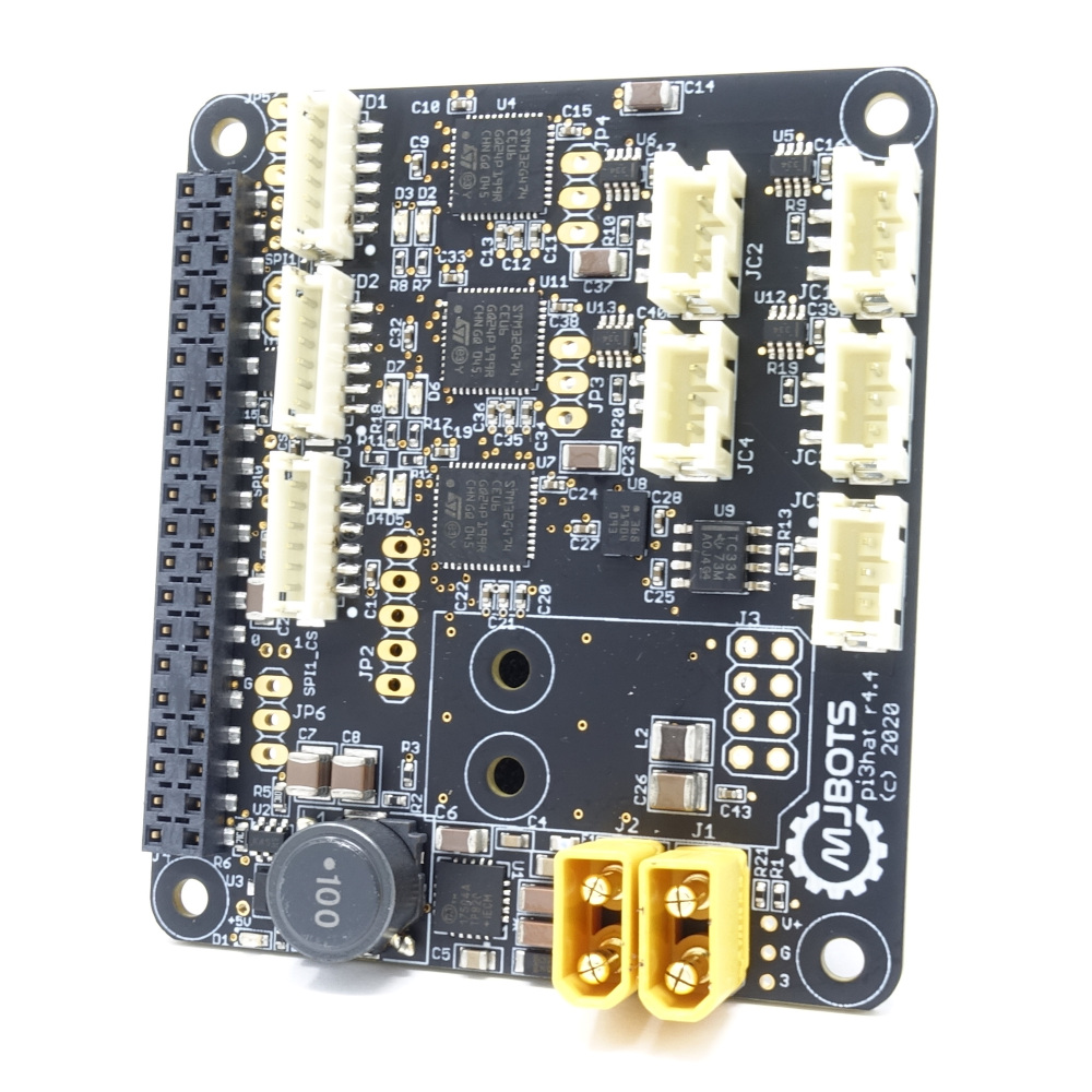
  • Increased voltage range: moteus r4.5 and the pi3hat both support 44V, so any new power_dist board should support at least that.
  • Lower quiescent current: Ideally, the quiescent current would be measured in microamps, or at least at a level that it does not confuse BMS systems.
  • Energy monitoring: Often in the development of the quad A1, I wanted to have a system level power and energy monitoring solution so as to identify the energy cost of various maneuvers and gaits. Tracking that at the power_dist level seems like a logical place.
  • Wider load envelope: The 3.1 version had a relatively limited maximum downstream capacitance and turn-on current draw. It was enough to power on 12 moteus controllers and a small computer, but not much else.

To achieve these goals, I decided to try using what is known as a “hot swap controller”. These are integrated circuits that are intended for use in cards that plug into server backplanes. Given that any given card could potentially have a large decoupling capacitance, inserting it live into a backplane could cause arcing, and high currents that cause the overall bus voltage to drop outside of tolerable limits.

Development of next-gen power_dist (part 1)

The current iteration of the mjbots power_dist board released back in the summer of 2020 is pretty useful. It pre-charges the input, provides a soft switch, and gives you a bunch of output connectors to make wiring easier.

r3.1 Limitations

However, this version did have some limitations and potential problems. The first is that the pre-charge method it uses, a simple on/off pre-charge resistor, is unable to support a wide range of supply voltages. Either the resistor has a low value, in which case large input voltages will cause thermal failure, or for larger values, it isn’t able to actually pre-charge the bus sufficiently before engaging the primary MOSFET.

moteus position anti-windup

The moteus controller uses a somewhat unique integrated position / velocity / torque controller with per-command configurable proportional and derivative gains. Through various combinations of these settings, it can emulate many different types of controllers, but one that it has struggled with until now was a pure velocity controller.

It has been minimally possible to use moteus as a purely velocity controlled since wraparound support was implemented, but that came with a caveat. Either the proportional term needed to be set to 0, in which case velocity tracking performance was poor, or if the proportional term was non-zero, an external torque would cause the position to drift arbitrarily far from the target position. Then if the external torque were released, the controller would “catch up” for all the lost ground, moving very rapidly.

pi3hat configurable CAN

To date, the pi3hat CAN channels only supported CAN properties suitable for use with moteus controllers. Given that’s what most people are using them for, that’s fine. However, there was no real constraint behind that, just laziness.

Thus, I’ve released new firmware for the pi3hat that supports configuring the bitrate, FD-ness, and other properties of all 5 CAN channels.

Currently only the C++ library exposes the configuration functionality, but it will be easy enough to add to python when someone needs it.

pi3hat r4.4

It seems like all the posts I’m writing these days are for new products! Here’s the pi3hat r4.4:

There are two changes from the previous r4.2. First, it now supports voltage inputs up to 44V. Second, in support of future upgrades, the 5th CAN-FD port has been upgraded to support 8Mbps, but downgraded to no longer have a wide common mode voltage range.

THUS, IT IS NOT SAFE TO CONNECT THE CAN-FD PORT ON THE pi3hat r4.4 TO A power_dist r3.X BOARD.

qdd100 beta 2

I’d like to introduce the qdd100 beta 2!

This is the newest version of a quasi-direct-drive servo from mjbots. It has a sleek new look, and improved performance all around:

Beta 1 Beta 2
Peak Torque 12.5 Nm 16 Nm
Backlash +- 0.2 degrees +- 0.1 degrees
Voltage Range 10-34V 10-44V
Mass 470g 475g

Comparison from beta 1 to the new beta 2

Additionally, the M3 mounting holes are now 3mm deep instead of the previous 2mm, which gives more flexibility when designing mounts.

moteus firmware release 2021-01-14

Sometimes you find bugs, and sometimes the bugs find you! While getting ready to release some updated qdd100 beta servos, I was investigating speed control in the moteus firmware and discovered an unwelcome surprise!

Voltage feedforward

To improve dynamic response under high accelerations, moteus uses a voltage feedforward term as part of its control loop. When trying to command a specific current, it normally applies a PI controller to determine the resulting D and Q phase voltages to apply. The feedforward component of this looks at the phase resistance and the current rotor velocity, and determines a zeroth order estimate of what voltage would be required to achieve that current under a no-load condition, only using the PI controller to determine the difference.

power_dist load test circuit

While testing some variants and new versions of the power_dist board, I wanted to be able to simulate the types of loads that it experiences with a fully loaded robot. Some things are easy, like this capacitor attached to an XT30 connector:

I also have giant power resistors in a similar form factor:

However, a dumb load resistor isn’t a particularly representative load. Most likely, the loads that a power_dist will drive are active loads with switching regulators. When the output voltage is lower, the current will be correspondingly higher. That is especially important when validating pre-charge behavior, because it means that the current is much higher during the initial pre-charge window than it would be for a pure resistive load.