Archives: 2021

Auxiliary encoders for moteus

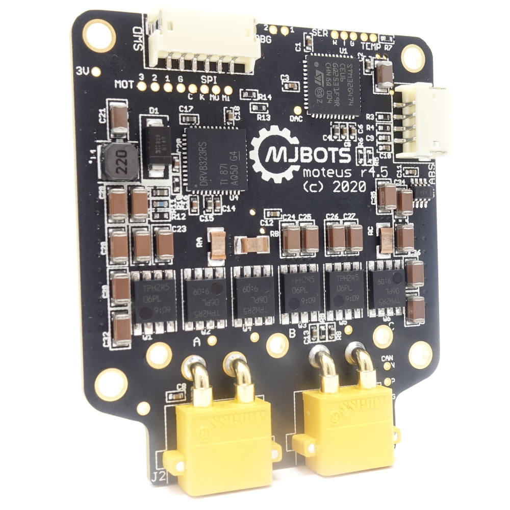
The moteus controller uses an absolute magnetic encoder to sense the position of the rotor in order to conduct field oriented control of the motor. In many applications, this sensing is also sufficient to measure the output as well, particularly in direct drive applications. However, if the controller is driving the output through a gear reduction, multiple turns of the input are necessary to make one turn on the output. At power on, this results in an ambiguity, where the controller doesn’t know where the output is.

New available limits in moteus firmware

Some of the new features in the moteus 2021-04-09 firmware release are new limits that can make the overall system more robust to faults or environmental conditions.

Velocity limiting

config: servo.max_velocity

Like the position limits, there now is a configurable velocity limit. If the motor is moving faster than this limit in either direction, then the applied torque will be limited, eventually to a value of 0. This can be used to reduce the likelihood of runaway behavior in systems where high speeds are not expected.

Improved qdd100 packaging

There are a lot of steps necessary to get a product to market, not just a fancy render. I admit to being far from covering all the bases yet, but we’re getting there. In that spirit, I recently upped the packaging game of the qdd100 with some custom boxes and foam inserts. Pick one up at mjbots.com!

Auto-tuning current control loops

Since the moteus controller was first released, it has implemented a two-stage controller. The outer loop is a combined position/velocity/torque PID controller, which takes as an input a position trajectory, and outputs a desired torque. The inner loops accepts this torque, and uses a PI controller to generate the Q phase voltage necessary to achieve that torque.

Until now, the constants for that PI controller were left as an exercise for the reader. i.e. there were some semi-sensible defaults, but the end-user ultimately had to manually select those constants to achieve a given torque bandwidth. That isn’t too much of a problem for a sophisticated user, but for the rest of us, it is hard to know how to go from a desired torque bandwidth to reasonable PI gains.

Unsuccessful CAN-FD communication between CANBed-FD and moteus

On the mjbots discord, people are often looking for the cheapest possible way to command and monitor a moteus controller. One possible solution that comes up over and over again is the CANBed-FD board, as sold by Seeed Studio (and others). I decided to get one of these in house to see if I could make it work:

The first thing I figured out was that the DB-9 connector used a non-standard pinout for CAN_L and CAN_H. I just switched to the terminal block connections instead of the DB-9 to get around that. For the software, I decided to use the acan2517FD Arduino library, as it was quite a bit more robust and featureful than the one provided by Longan Labs.

mjbots power_dist r4.3b

I’d like to introduce the newest mjbots product, an updated revision of the power_dist, 4.3b available at mjbots.com today!

This version has a number of improvements over the previously released r3.1:

r4.3b r3.1
Voltage Range 10-44V 8-34V
Maximum load capacitance 4,000 uF 400 uF
Quiescent Current 300uA 5mA
Current (Continuous / Peak) 45A / 80A unrated / 100A
Energy Monitoring YES NO
Switch Mode High Side Low Side
Dimensions 50x80mm 45x70mm
Price $139 $79

The only real downsides are that is more expensive and slightly larger.

Failed power_dist r4 designs (part 4)

For context, see part 1, part 2, or part 3.

r4.0

My first attempt at an r4 design was based on the TI LM5066 hot swap controller. It is one of the more full featured controllers, since it supports built in energy monitoring over a SPI bus with no additional components. This first iteration was actually surprisingly close to being workable. There were two factors that it performed poorly on, quiescent current and energy monitoring. The quiescent current was similar to the r3.1 version. Energy monitoring was present, but at the full scale range necessary for power_dist, it was almost unusably inaccurate. With a design set for a peak of 100A, and also the lower 25mV current sense range, the current noise was measured in multiple amps.

Hot swap controllers (next get power_dist part 3)

This is one of a series covering the new mjbots power_dist board. See part 1 and part 2 for more context.

As mentioned previously, hot swap controllers are primarily used to allow a card to be inserted live into a server backplane, while minimizing disruption to the primary power bus while doing so. Additionally, they often implement protection features like over-current and short-circuit protection, and some support energy monitoring.

Typical topology

A typical hot-swap topology looks like: