Archives: 2020

Quad feet construction fixture

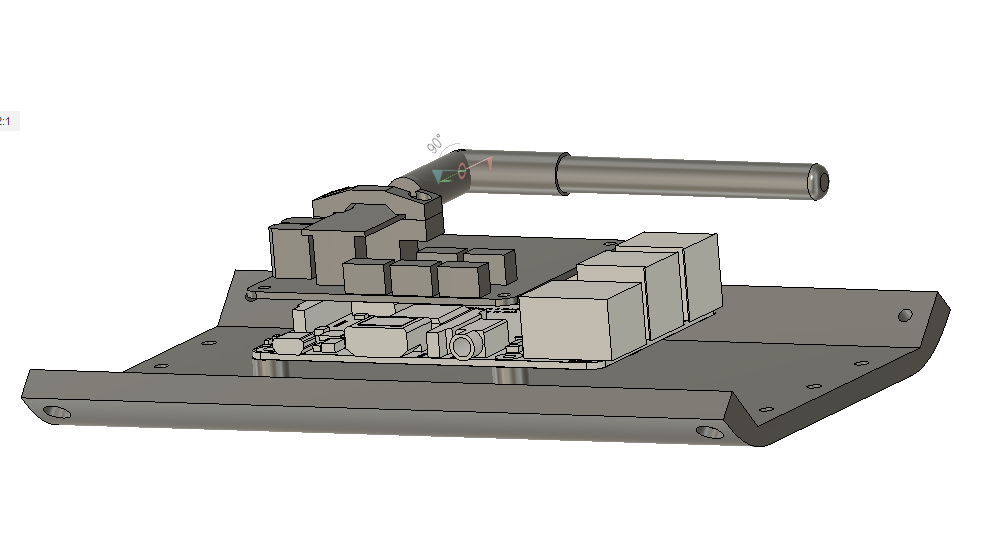
The quad A1 was the first robot I built with foam cast feet.  When I did the first feet, I jury rigged a fixture from some old toilet paper rolls to hold things in place while they were curing.  When I went to rebuild with my most recent leg geometry, I figured it was time to get at least a little more serious.  Thus, my new leg casting fixture:

dsc_0578

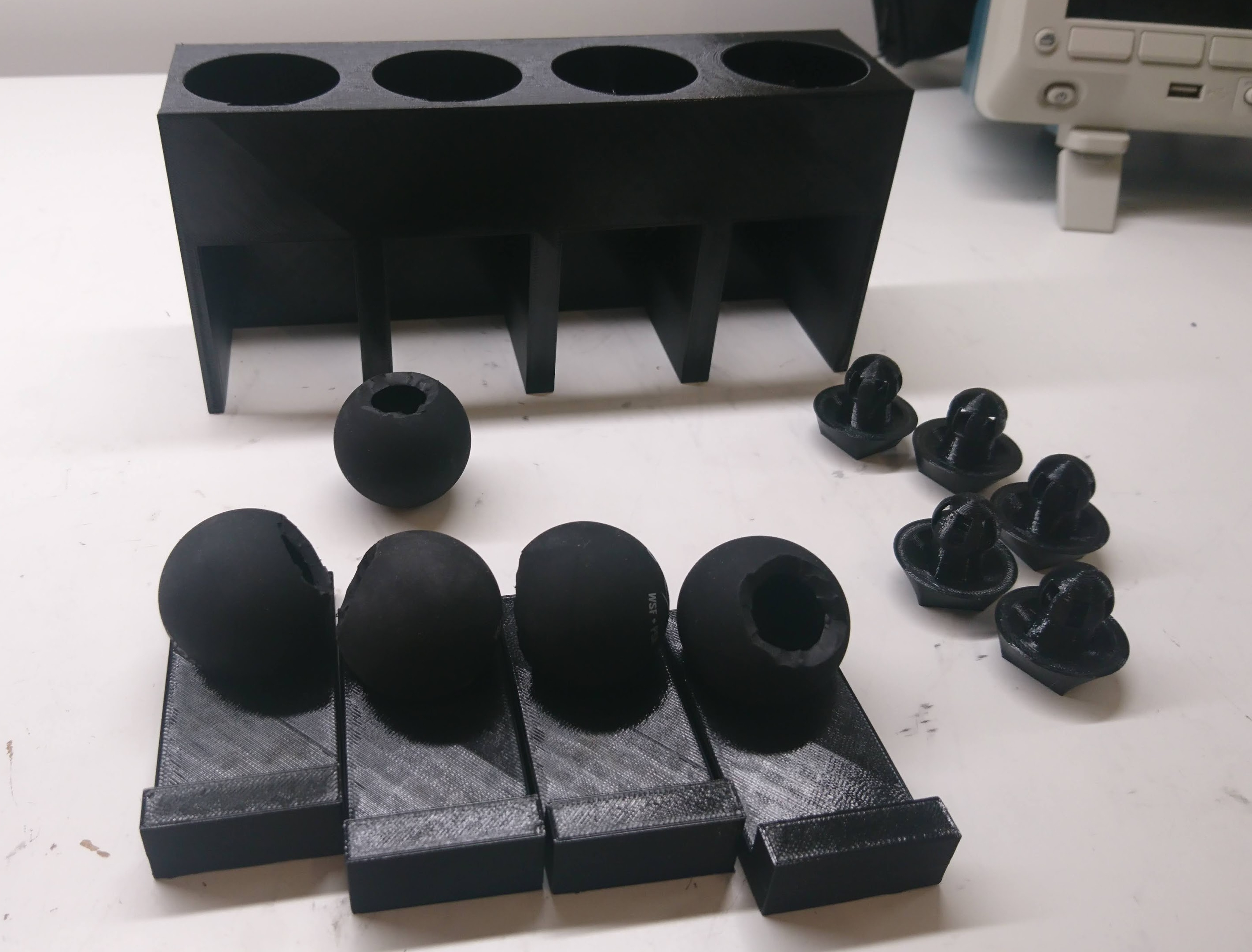
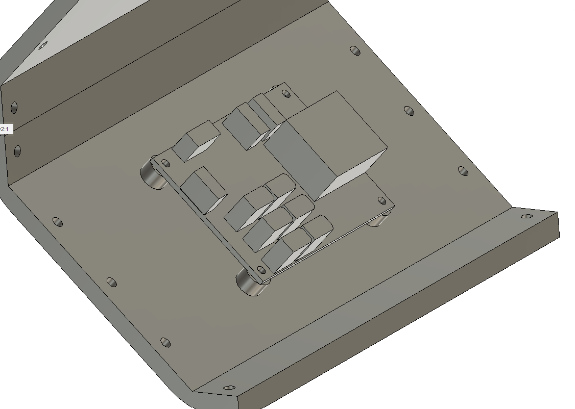
When an insert is cast into place, it is set on one of the trays, the tray is inserted into a slot, and then a weight can be placed on top and constrained by the fixture.

Primitive turret automatic tracking

Continuing in my series of developments with the Mech Warfare turret, I’ve now managed to replicate the primitive target tracking functionality I had in the v2 version of the turret.  This works using a pretty simple principle:

  • raspicam is used to read the raspberry pi camera
  • ArUco is used to find any fiducials in view
  • The target closest to the center is deemed, the “active target”
  • The pitch and yaw rate are set based on a simple P controller to bring that target to a known point

This works passably, as shown in the video below:

quad A1 chassis updates

I finally got around to fixing a number of minor glitches in the quad A1’s chassis recently.

1. The raspberry pi is now far enough away from the left panel that you can connect the HDMI if you choose.

20200506-rpi_mounting

2. I no longer have vestigal studs for the pre quad A0 junction board on the other side.

20200506-power_dist

3. The switch got moved down to between the legs.

dsc_0631

Leg zeroing fixture

As part of provisioning a quad A1, or anytime the mechanical configuration has been changed, I need to go and record where the zero position of all the joints is.  The “0” position for the software now is with the shoulders perfectly horizontal, and the upper and lower leg sticking straight down.

Up until now, every time I’ve done this it has just been by eyeballing and with lots of foam and bubble wrap to shim things into place long enough to record the level.  Sometimes I had to go back and try a few times, as even determining when something is straight is not, well, straightforward.

Programming and testing moteus controllers

Like with the fdcanusb, I built a programming and test fixture for the moteus controllers.  The basic setup is similar to the fdcanusb.  I have a raspberry pi with a touchscreen connected via USB to a number of peripherals.  In this case, there is a STM32 programmer, a fdcanusb, and a label printer.  Here though, unlike with the fdcanusb fixture, I wanted to be able to test the drive stage of the controllers and the encoders too.

nrfusb multiple slave support

The Mech Warfare turret concept I’m developing involves having basically two independent robots, the actual robot and the turret.  To make that be controllable in a sane way, the control station will command and receive telemetry from both simultaneously, allowing control actions to be given in the camera frame of reference.  Otherwise, remote piloting is… very challenging.

This could be done just by having two separate transmitters.  Since the nrfusb that I’m using is spread spectrum, many transmitters can easily co-exist at the same time.  However, the protocol is designed such that a single transmitter can simultaneously communicate with multiple slaves at the same time, simply by switching channels more frequently.

Turret active inertial stabilization

This post will be short, because it is just re-implementing the functionality I had in my turrets version 1 and 2, but this time using the raspberry pi as the master controller and two moteus controllers on each gimbal axis.

I have the raspberry pi running the primary control loop at 400Hz.  At each time step it reads the IMU from the pi3 hat, and reads the current state of each servo (although it doesn’t actually use the servo state at the moment).  It then runs a simple PID control loop on each axis, aiming to achieve a desired position and rate, which results in a torque command that is sent to each servo.  Here’s the video proof!

moteus controllers with gimbal motors

To date, I’ve used the moteus controllers exclusively for joints in dynamic quadrupedal robots.  However, they are a relatively general purpose controller when you need something that is compact with an integrated magnetic encoder.  For the v3 of my Mech Warfare turret I’m using the moteus controllers in a slightly new configuration, with a gimbal motor, one for each of the pitch and yaw axes.

Gimbal motor theory and current sensing

From an electrical perspective, gimbal motors are not that all that different from regularly wound brushless outrunners.  The primary difference being that they are wound with a much higher winding resistance.  That enables them to be driven with a much lower current, at the expense of a lower maximum angular velocity.  In this case, I’m using the GM3506 from iFlight which has a winding resistance of 6 ohms, that results in working currents being on the order of 2A maximum.

New Mech Warfare turret

Another of the tasks I’ve set for myself with regards to future Mech Warfare competitions is redesigning the turret.  The previous turret I built had some novel technical features, such as active inertial gimbal stabilization and automatic optical target tracking, however it had some problems too.  The biggest one for my purposes now, was that it still used the old RS485 based protocol and not the new CAN-FD based one.  Second, the turret had some dynamic stability and rigidity issues.  The magazine consisted of an aluminum tube sticking out of the top which made the entire thing very top heavy.  The 3d printed fork is the same I one I had made at Shapeways 5 years ago.  It is amazingly flexible in the lateral direction, which results in a lot of undesired oscillation if the base platform isn’t perfectly stable.  I’ve learned a lot about 3d printing and mechanical design in the meantime (but of course still have a seemingly infinite amount more to learn!) and think I can do better.  Finally, cable management between the top and bottom was always challenging.  You want to have a large range of motion, but keeping power and data flowing between the two rotating sections was never easy.

Updated quad pi3 hat

I made a number of tweaks to the quad A1’s raspberry pi hat to get it ready for production, resulting in r4.1 of the board:

dsc_0491

None of the changes were particularly big, but each has some value:

  • The correct switch mode regulator is installed.
  • The auxiliary CAN transceiver was switched to one that supports a larger common mode voltage.  This will allow it to be connected to the power distribution board without smoking.
  • Each of the STM32s now has some GPIO pins connected directly to GPIOs on the raspberry PI primarily to be used for interrupts.
  • Pin headers expose a few gpio pins from each STM32 for interfacing with random external things.
  • The NRF radio module changed orientation and has improved power filtering.
  • I added a microphone to the auxiliary STM32.  The goal is to eventually be able to use that to synchronize external video with onboard data collected during operation more easily.

I’ll bring this up in a future post!