Archives: 2020

fdcanusb up at mjbots.com

I’ve received my first production run of the fdcanusb CAN-FD USB adapters and they are up for sale at mjbots.com!

fdcanusb_angle

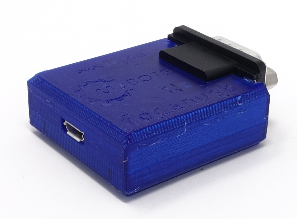
While this is necessary for interacting with the moteus controller, it is also a fine general purpose CAN-FD adapter.  At the moment, the USB interface is a platform independent line based serial one (Windows, Linux, MacOS).  It doesn’t yet interoperate with SocketCAN on linux, but hopefully that will be resolved in the not too distant future.

New machine day: Vibratory tumbler

To date with my machined parts, I’ve mostly left everything in an “as-machined” state.  As I get ready to make some servos where I care at least a little about how they look, I decided to invest a little in surface finish options.  I started using some Scotch-Brite, which gave passable results for some components, but it was hard to be consistent and the final results were always somewhat anisotropic.

Pre-production mk2 servos

To build a second demonstration quadruped and to generate some development kits, I’ve built up a set of 20 of the mk2 servo.  The production process is working out fairly well, in fact slightly better than I had predicted for overall cycle time.  The servos so far are coming out great, moving smoothly with full power.

Shafts inserted into the planet input

Shafts inserted into the planet input

Output bearing on the planet outputs

Output bearing on the planet outputs

All parts for pre-production mk2 servo in house

I’m planning on building up a set of mk2 servos to test them on a quadruped and make some development kits.  As of now, I’ve got all the materials in house for the build and many things partially assembled!

A bunch of back housings

A bunch of back housings

Back covers post-brushing

Back covers post-brushing

A bunch of planet inputs

A bunch of planet inputs

A test of the final finish of the outer housing

A test of the final finish of the outer housing

3D printed camera mounting bracket

To help get some better overhead camera shots, I made a simple bracket that I could bolt to my over-desk bookshelves.  It just has a 20mm tube on it that various camera attachments can be bolted to:

dsc_0256dsc_0257

Here’s to more camera angles!

Final lower leg assembly

After casting the feet, the final step was to join the lower leg with the 3d printed foot bracket.  This I just did with some slow cure epoxy.

dsc_0280

It seems strong enough for now, I was able to manually apply 10kg of load to a single leg while perfectly horizontal with no signs of stress, which should be good enough for a 4g 4 legged jump.

All the legs (and a spare) are now assembled with belts and a lower pulley ready to go on a robot!

Casting feet

Previously, I described the overall plan for my improved foot.  To make that work, I needed to cast a 3d printed part into the squash ball such that it would likely stay attached during operation, be suitable rigid and yet damped, and do so repeatably.

To start with, I used a random single yellow dot squash ball with a hole cut in one side using a pair of side cutters.  For the casting foam, I just used Smooth-On Flex Foam-IT 17, which is what Ben Katz originally used at least.  Initially I just mixed up a batch, poured it in to a random level, stuck my bracket in and hoped for the best.

quad A0 - Improved foot design

As mentioned long ago in my post on failing more gracefully, it was obvious I wanted to strengthen the lower leg and foot mechanism to remove the point of failure observed there.  For now, I’m attempting to basically copy the original Mini-Cheetah foot principle, although with more 3d printing and less machining.

20200211-mk2-foot

The basic idea is to print the entire lower leg in a single go laying on its side, so that delamination is unlikely.  The foot bracket will be cast into a squash ball, then epoxied onto the lower leg.

mk2 leg knee stud

One of the parts on the original quad A0’s leg that was prone to failure was the “knee stud”, a little cylinder that acted as the mating interface between the upper leg and the lower leg.  It directly attaches to the upper leg, and has bearings that ride between it and the lower leg.  The entire tension of the leg belt is born in shear by this part.

20200206-knee-stud

In the mk1 leg, this part was 3d printed with heat set inserts used to form the threaded holes.  This mostly worked, although occasionally the stud could shear along the 3d printed lamination lines.  Thus, for the mk2 leg, I’m making this part out of 6061.

Updated leg design for mk2 servo

Since the mk2 moteus servo has slightly different dimensions and a different mounting pattern than my original, I needed up update the full rotation leg design to handle it.  The basic concept is the same, except for some in-progress work on the foot design which I’ll write up later.  The only significant changes were that because of the mk2 design, access to the power and data connectors is much easier.

Here’s a brief CAD snapshot: