Archives: 2020

nrfusb

In order to bring up the final piece of the raspberry pi 3 hat, the nrf24l01+, I wanted a desktop development platform that would allow for system bringup and also be useful as a PC side transmitter.  Thus, the nrfusb:

dsc_0367

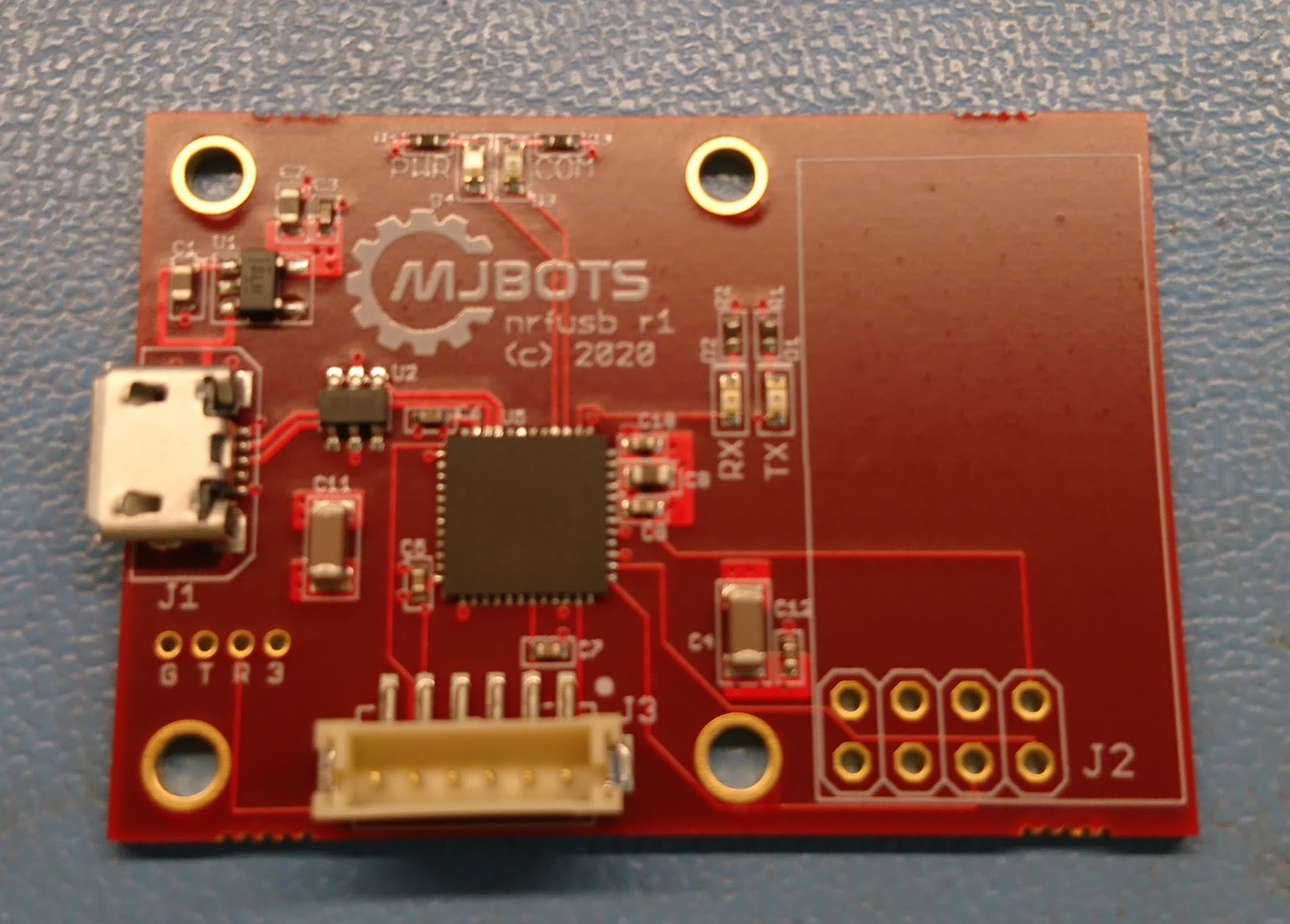
Similar to the fdcanusb, it is just an STM32G474 on the USB bus, although this has a pin header for a common nrf24l01+ form factor daughterboard.

The next steps here are to get this working at all, then implement a spread spectrum bidirectional protocol for control and telemetry.

Simple walking gait on the quad A1

After I restructured my control laws to take advantage of high rate force feedback for the pronking experiments, I haven’t actually managed to port the walking gait yet.  Now that I have a brand new robot, it seemed like a good time!

This gait is basically the same thing as I ran on the quad A0 in principle.  The opposing feet are picked up according to a rigid schedule, and moved to a point opposite their “idle” position based on the current movement speed.  Any feet that are completely placed on the ground just move with the inverse of the robot’s velocity.

quad A1: First movement

After getting all the legs swapped out, I ran my existing software to validate that all the pieces worked together.  Here’s a quick video showing basically what I’ve shown before, but with all new hardware:

Building the quad A1

Now that I have a bunch of the mk2 servos set and ready to go, a new leg design, a new power distribution board to power them, and a raspberry pi3 hat to communicate with them, I built a new quadruped!  I’m calling this the mjbots quad A1, since basically everything is upgraded.

dsc_0362

After I initially assembled the new legs onto the chassis, I realized I had the geometry slightly off and there was some interference through part of the shoulder rotation.  I made up new printed parts and replaced everything in front of the camera.  Thus, watch some high speed robot surgery:

Attitude estimation for pi3 hat

Now that the IMU is functioning, my next step is to use that to produce an attitude estimate.  Here, I dusted off my [unscented Kalman filter](http://unscented Kalman filter) based estimator from long ago, and adapted it slightly to run on an STM32.  As before, I used a UKF instead of the more traditional EKF not because of its superior filtering performance, but because of the flexibility it allows with the process and measurement functions.  Unlike the EKF, the UKF is purely numerical, so no derivation of Jacobians is necessary.  It turns out that even an STM32 has plenty of processing power to do this for things like a 7 state attitude filter.

Bringing up CAN on the quad pi3 hat

After getting the power to work, the next step in bringing up the new quad’s raspberry pi interface board is getting the FDCAN ports to work.  As described in my last roadmap, this board has multiple independent FDCAN buses.  There are 2 STM32G4’s each with 2 FDCAN buses so that every leg gets a separate bus.  There is a 5th auxiliary bus for any other peripherals driven from a third STM32G4.  All 3 of the STM32G4’s communicate with the raspberry pi as SPI slaves.

Bringing up the IMU on the pi3 hat

The next peripheral to get working on the quad’s raspberry pi interface board is the IMU. When operating, the IMU will primarily be used to determine attitude and angular pitch and roll rates.  Secondarily, it will determine yaw rate, although there is no provision within the IMU to determine absolute yaw.

To accomplish this, the board has a BMI088 6 axis accelerometer and gyroscope attached via SPI to the auxiliary STM32G4 along with discrete connections for interrupts.  This chip has 16 bit resolution for both sensors, decent claimed noise characteristics, and supposedly the ability to better reject high frequency vibrations as seen in robotic applications.  I am currently running the gyroscope at 1kHz, and the accelerometer at 800Hz.  The IMU is driven off the gyroscope, with the accelerometer sampled whenever the gyroscope has new data available.

Bringing up power on the quad pi3 hat

The first thing I needed to get working on the new quad’s raspberry pi3 hat, was the input DC/DC power converter.  One of the main functions of this board is to take the main DC bus voltage of around 20V, and provide the raspberry pi with 5V power.

In the previous iteration of this board, it was limited to an recommended maximum voltage of around 24V.  As with all the components in my hardware revisions I aimed to support a higher input voltage.  Here I switched parts to the Diodes AP64351 so that I could get to a recommended maximum voltage of 32V (the part’s absolute max is 40V).

New quad raspberry pi interface board

With the new FD-CAN based moteus controllers I need a way for the raspberry pi to communicate with them.  Thus I’ve got a new adapter board in house that I’m bringing up:

dsc_0339

This one has 5 independent FD-CAN channels, an IMU, a port for an nrf2401l RF transceiver as well as a buck converter to power the computer from the main battery bus.

The prototypes were largely constructed by MacroFab, although I did the Amass connectors and the STM32s because supply chain issues prevented me from getting those parts to MacroFab in time.

Programming a lot of fdcanusbs

To get ready for the initial limited release of fdcanusbs, I needed to program a whole bunch of them.  Further, I wanted to be able to scale up a few factors of two without being too annoyed with manual steps.  Thus, enter my minimal programming fixure:

dsc_0188

It isn’t much, just a raspberry pi 3b+, the official 7" rpi touch screen, a STM32 programmer, a “fixtured” fdcanusb to drive the device under test, and a label maker.  The touch screen is mostly there to display the results if anything goes awry, as in normal operation there is just one button to push.  The final cycle time to program a fdcanusb and install it into the enclosure is around two minutes, which is good enough for now.