Archives: 2019

Mech Warfare 2019 - at Maker Faire Bay Area

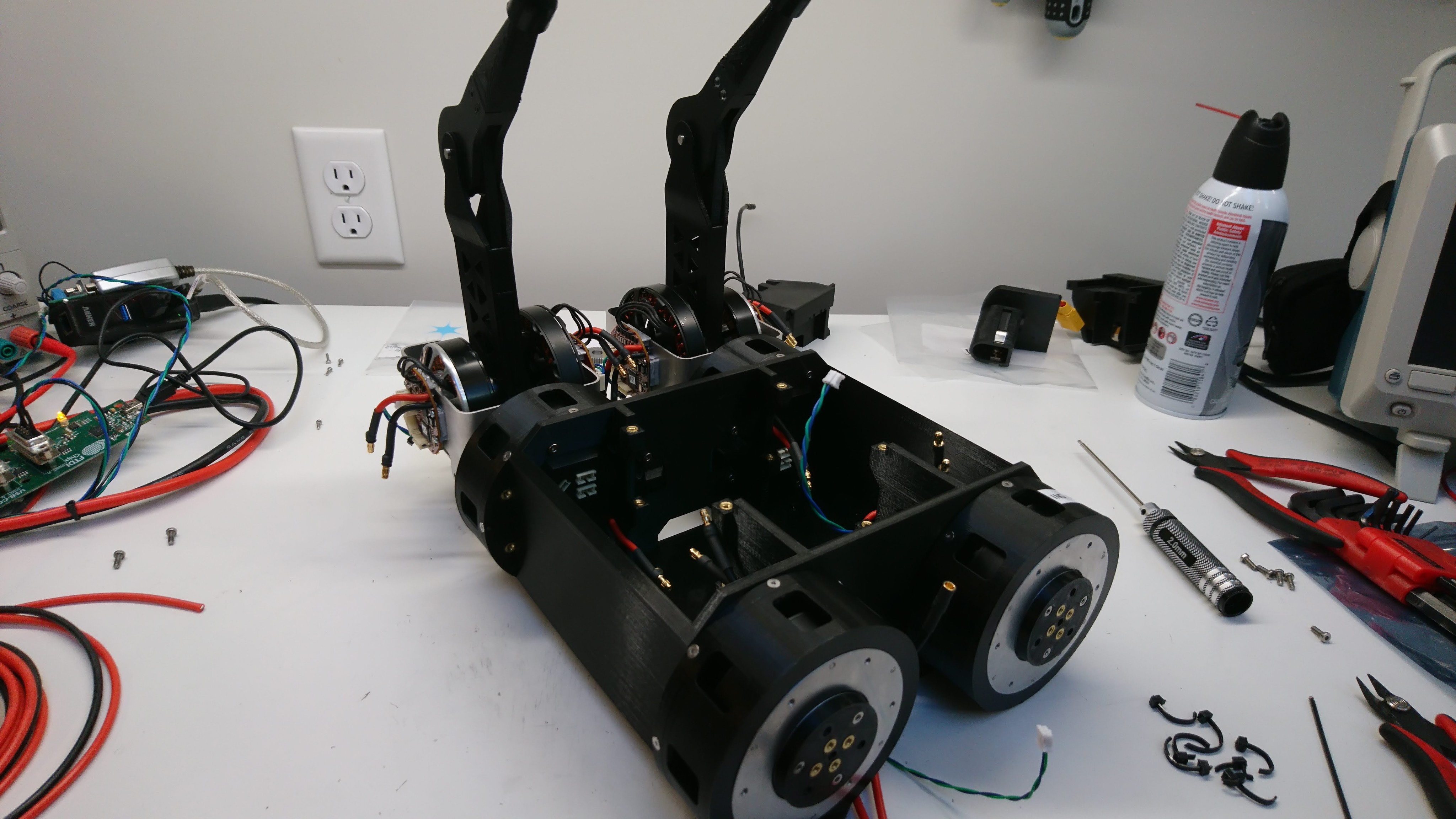
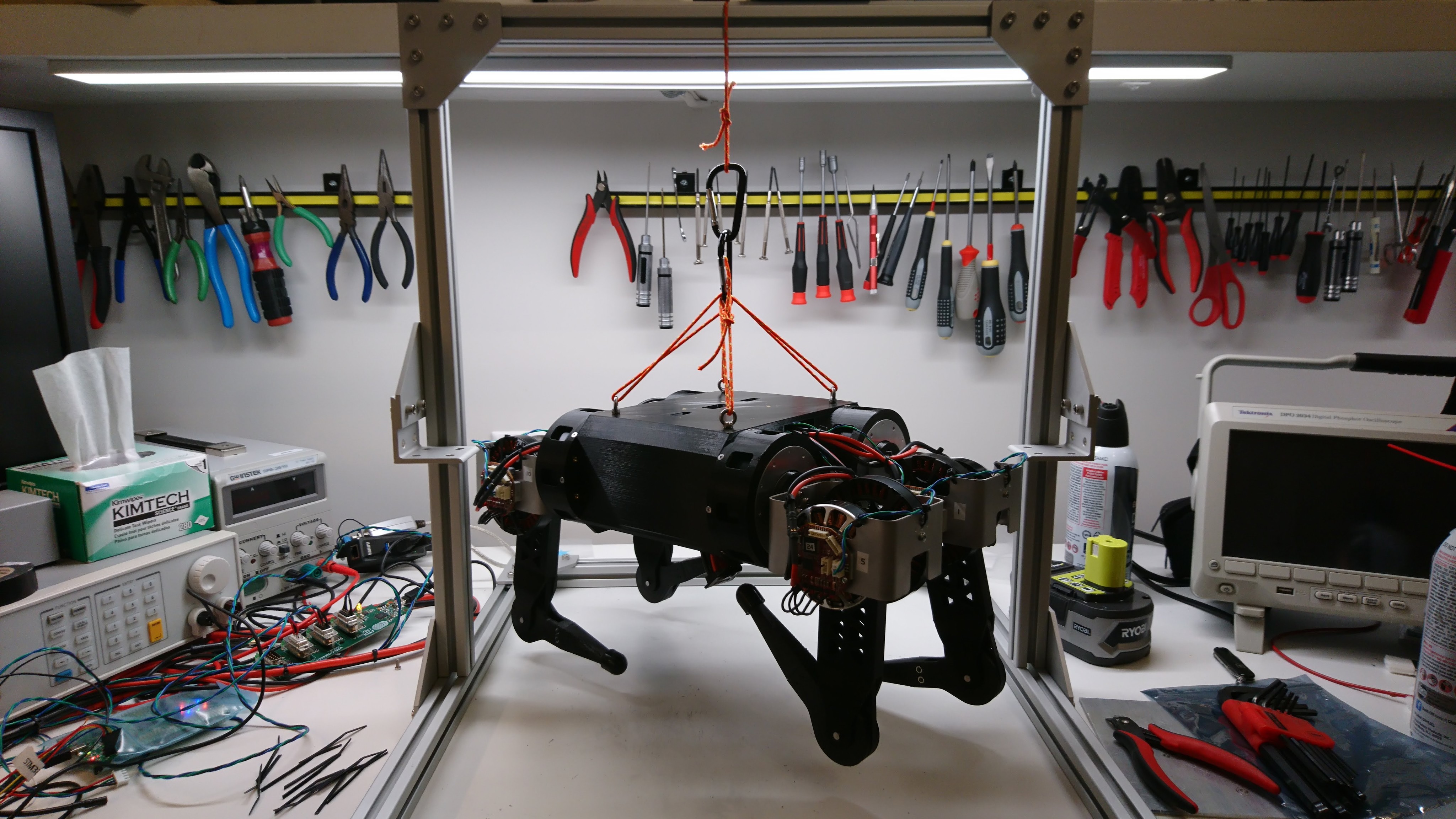
As an intermediate forcing function, I’ve been preparing Super Mega Microbot to enter the Mech Warfare event at Maker Faire Bay Area May 17-19 in San Mateo, CA!  The Mech Warfare event is a competition where scale size “mechs” or robots compete with airsoft cannons in a scaled down cityscape.  Teleoperation is allowed, but the human operators are only allowed to see “what the mech sees”, which means driving from a video screen.

rpi3 interface board

Now that I have a chassis that can walk a little bit, I need to get the onboard computer working.  To do that, I needed to update the raspberry pi 3 daughterboard I built for the previous turret for the new bus voltage and communication format.

The rpi3’s UART is incapable of controlling the direction line on the RS485 transceiver, so I added a small STM32 micro in line to control the transmit / receive direction.  It adds a little bit of latency, but testing the firmware I was able to get it down to only a byte’s worth or so.

First walking with gearbox chassis

Short recap: After building the quadruped with near-direct drive motors, I discovered that the lateral servos had insufficient position control authority to keep the robot standing up.  Thus I embarked on a now month long quest to design and build an integrated planetary gearbox.  At this point, I have enough gearboxes built for all the lateral servos, so it should be able to walk, right?

And tada!  It can!  Well, at least a little bit.  I’ve only spent a short while with the gearbox based chassis, and have a lot of work left to do.  However, here’s a quick video showing it walking around, slipping on a ruler, and almost falling over a few times.

Wiring up the gearbox chassis

Now that I had a set of 4 at least minimally working lateral servos, I needed to wire up the chassis so that everything had power and data.  Here are some pictures of that process:

Two legs installed

Two legs installed

Four legs installed

Four legs installed

Joint cable routing

Joint cable routing

Times four

Times four

Suspended from the test fixture

Suspended from the test fixture

Four sets of busbars, the junction board, and a shore power battery simulator

Four sets of busbars, the junction board, and a shore power battery simulator

log4cpp updates

While updating the mjmech code-base to interoperate with the moteus servos, I simultaneously was updating it to use C++17.  C++ rarely removes or deprecates features, but one of those which actually was removed in C++17, after being deprecated in C++11, was auto_ptr.  unique_ptr is strictly superior in all regards, and so there is no real reason not to switch.

However, mjmech depends upon a large amount of third party software.  Amazingly, only one package actually was broken by this removal of auto_ptr, log4cpp.  It actually saw some updates for C++17 compliance back in 2017, but otherwise hasn’t been updated since then.  I went ahead and forked it, and got it compiling with clang in C++17 mode at least:

Lateral servo gearbox build(s)

After completing one gearbox, I needed to build at least 4 more of them to replace the lateral servos on Super Mega Microbot (2).  So, I got to work.  First, I disassembled 5 more BE8108 motors.

dsc_2140

Then, I drilled out the rotors, this time using the mill at AA.

dsc_2145

Next I removed the stators from their backing.  This was painful enough last time, that I tried a new technique using the mill to do most of the work.  Unfortunately, one of the stators was critically damaged during my initial experimentation.  So, now down to 4 survivors.

Chassis for gearbox based lateral servos

dThe original chassis I had built for the brushless servo quadruped was designed around the aluminum bracket that was used in the Titan XOAR 6008 leg.  For a quadruped that uses the BE8108 gearbox for the lateral mechanism, a new attachment mechanism was necessary.  While I was at it, I made some other improvements as well.

  1. The battery is switched to use an off the shelf cordless power tool battery.
  2. The chassis is a shell, where most wiring can be run inside, including the IMU junction board.
  3. Dedicated inserts are in place on the top for a suspension fixture to be attached.

This was once again a record for the longest print I’ve made on my Prusa mk3s, 31 hours and change.

Rebuild of gearbox assembly

After finally getting the darned thing apart, and printing a new outer housing, I went about re-assembling the whole mechanism.  This time, I tried to take care to make the future disassembly less painful.

To start with, I filed down the problematic outer bearing interfaces of the sun gear holder so that the bearings were a slip fit over them.  These two interfaces don’t need to be particularly snug, so that was easy enough, if monotonous, to accomplish.  I also machined out a some pockets around the magnet hole, to make it possible to just hot-glue the position magnet in place and more easily extract it.

Rotor and stator alignment

Last time I covered getting to the point of having the rotor installed into the gearbox.  Here we’ll look at making it actually work in that configuration.

When I first got the rotor in place, it was clearly not centered properly.  Although much closer than in the plastic gearbox, it did interfere with the stator during a portion of a revolution.  The first obvious problem was that the primary shaft wasn’t making it all the way through the front shaft bearing.  That should have been an easy fix, but for two different very annoying reasons.