moteus servo mk2: Back housing
The back housing is the final piece of the moteus mk2 servo that I wanted to prototype. (The planet output is identical to the mk1, so I could use extra stock I had of it for the prototypes). It is large, and only mates directly to 4 other things, which makes it a little less complex than the front housing.
Design
I had initially designed the back housing to mate to the as-yet-unannounced new version of the moteus controller, the r4.x series. Unfortunately, I don’t have any of those working yet, so I tweaked the design to temporarily fit a r3.1 controller, which looks like this:
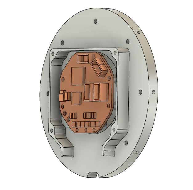
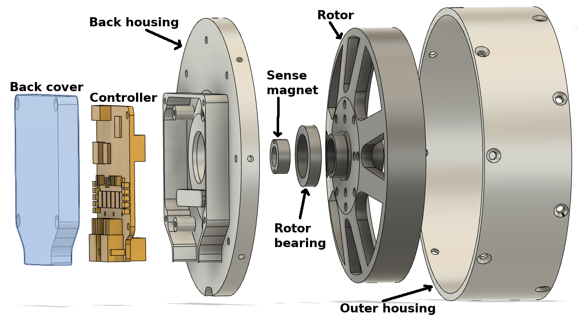
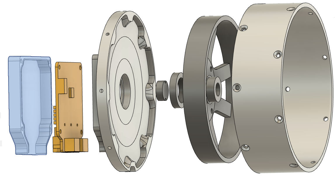
It mates to the rotor bearing in the center, the outer housing around the perimeter, provides support, mounting and heatsinking to the controller, and provides a mounting interface for the controller cover.
The only design intent change I made in the mk2 version here was to decouple the outer housing interface axially from the rotor bearing interface. In mk1, the back housing was a flat plate. Now in mk2, it is a very shallow cone, to slightly reduce the axial length of the large diameter outer housing and eventually make it possible to reduce the weight more because of it.
Manufacturing
Like the front housing, this was challenging to produce on the Pocket NC. It required even more steps than the front housing, since it had no final flat surface which also had threaded holes. Thus I ended up using a manual machining stage, followed by 3 operations on the Pocket NC.
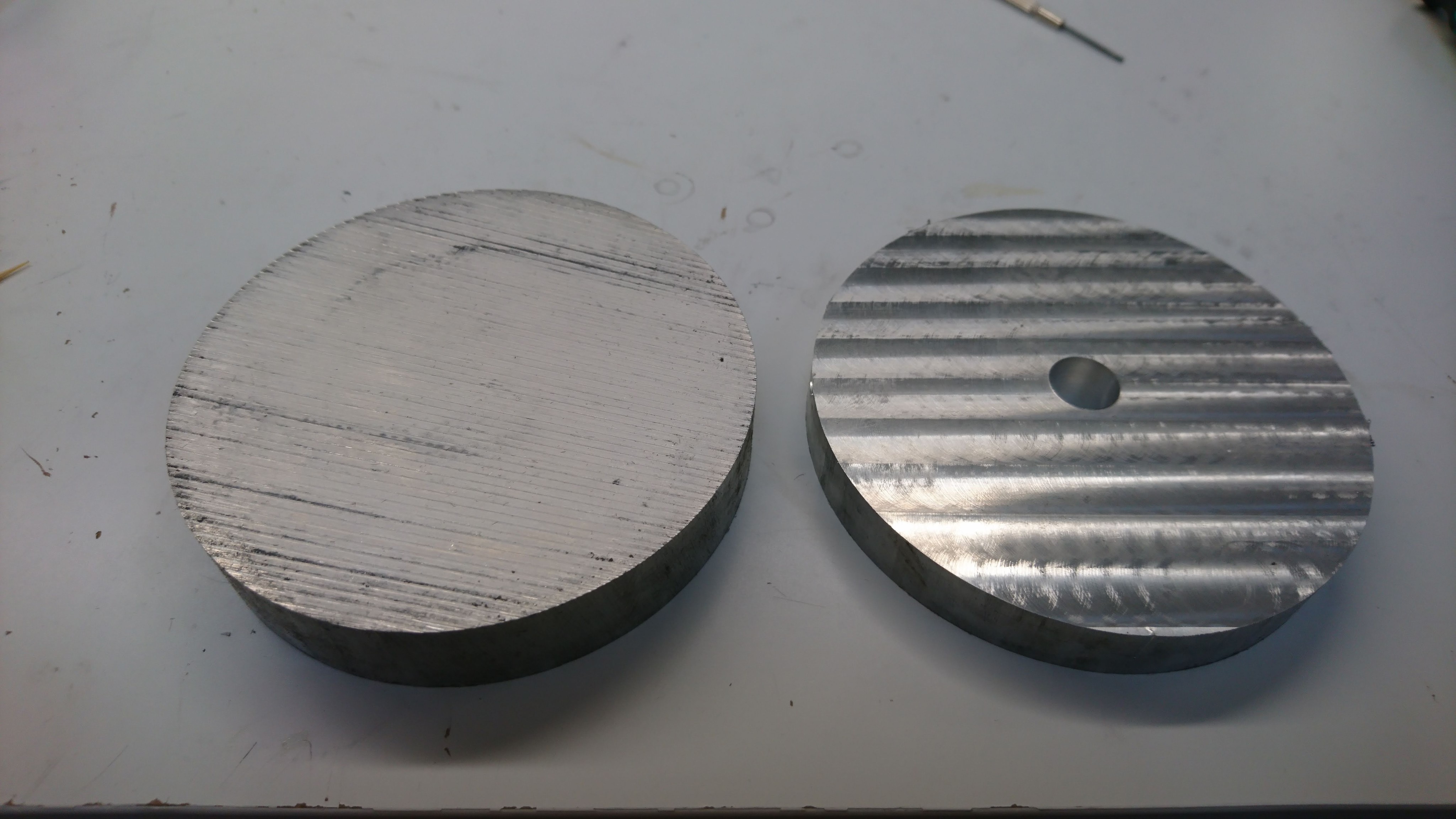
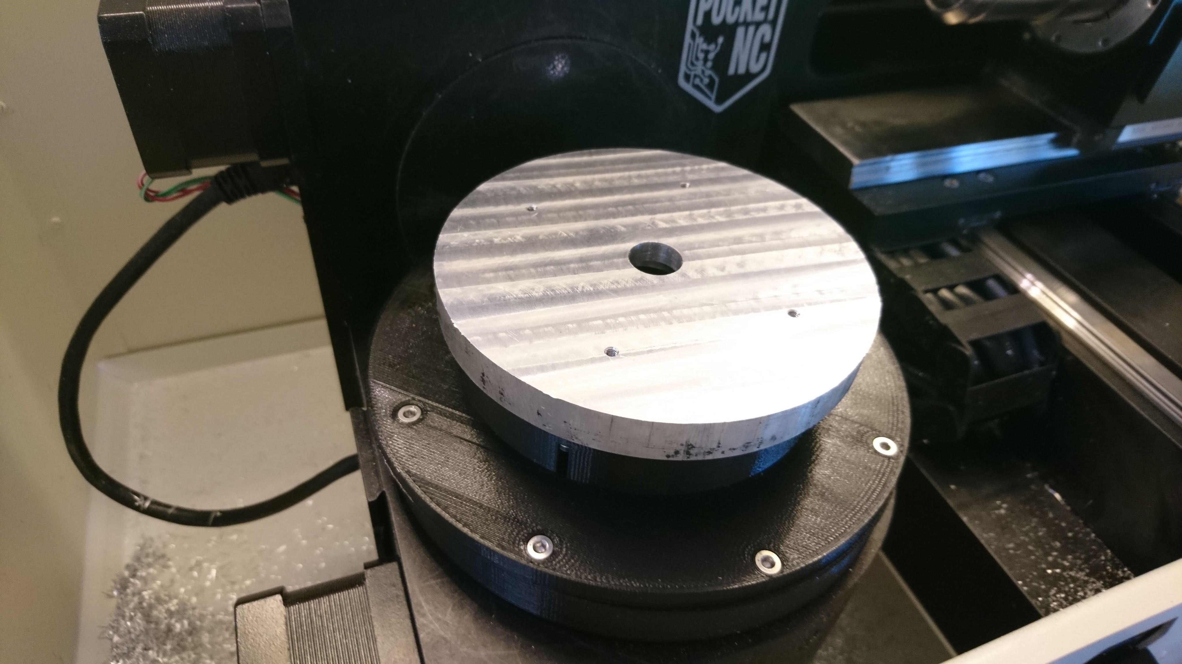
Manual machining
The manual machining merely took 4in round stock that was rough cut to 5/8" and faced it to approximately 15mm, then drilled a center 1/2" hole.
Operation 1
For the first Pocket NC operation, I used a 3d printed bracket to clamp the stock down, and then the four M2.5 holes used to secure the back cover were drilled and threaded. These will be used in the next operation.
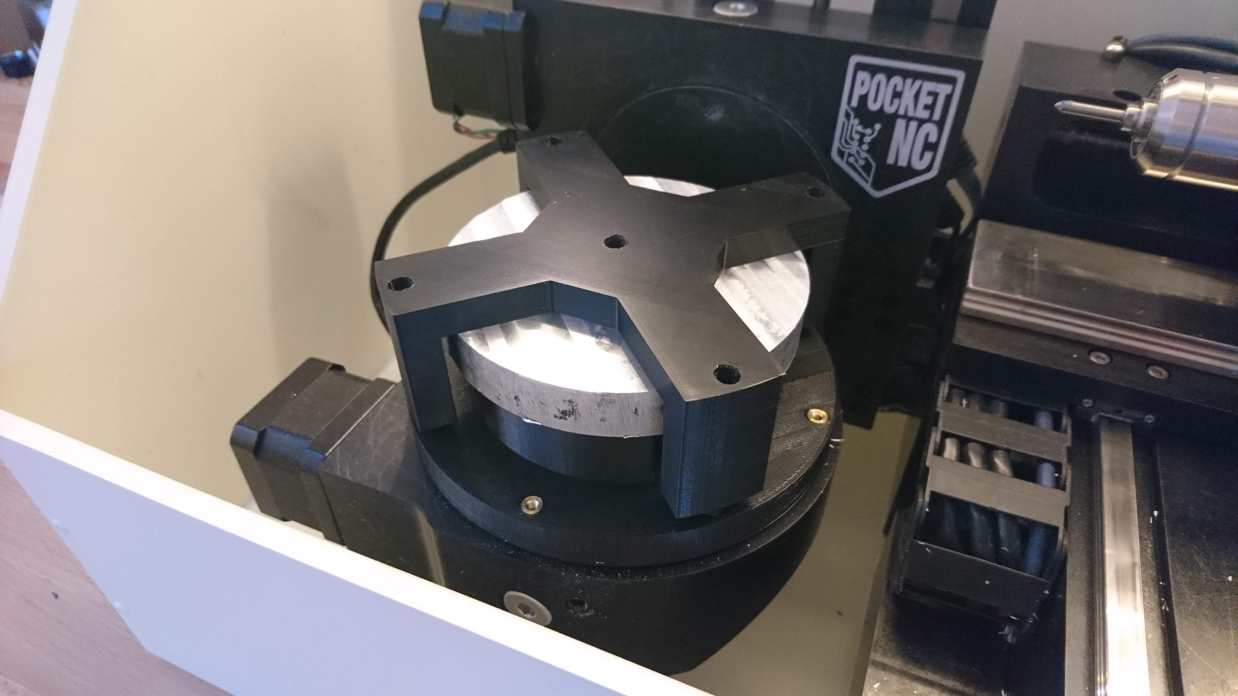
Operation 2
In operation 2, those holes were used to bolt the stock to another 3d printed fixture, which was then bolted to the same 3d printed assembly as used in operation 1 (and for the front housing).
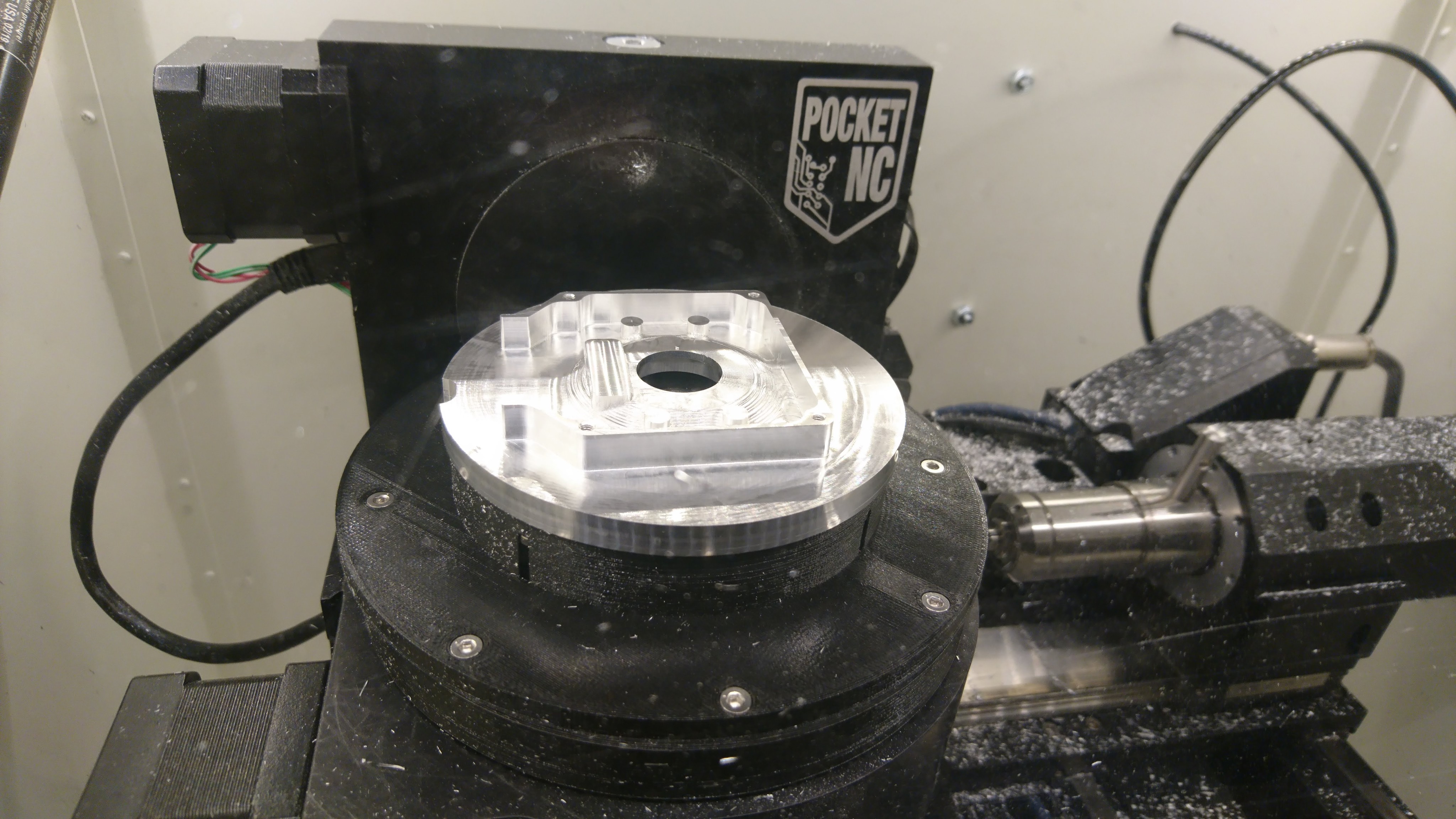
Operation 3
The final step of operation 2 drilled and threaded 4x M3 holes on the back surface purely for fixturing purposes. They are used to bolt the in-progress work to yet another fixture, so that the rest of the back can be machined.
Video
Here’s a video showing all the machining steps: