Archives: 2019-03

moteus RS485 bootloader

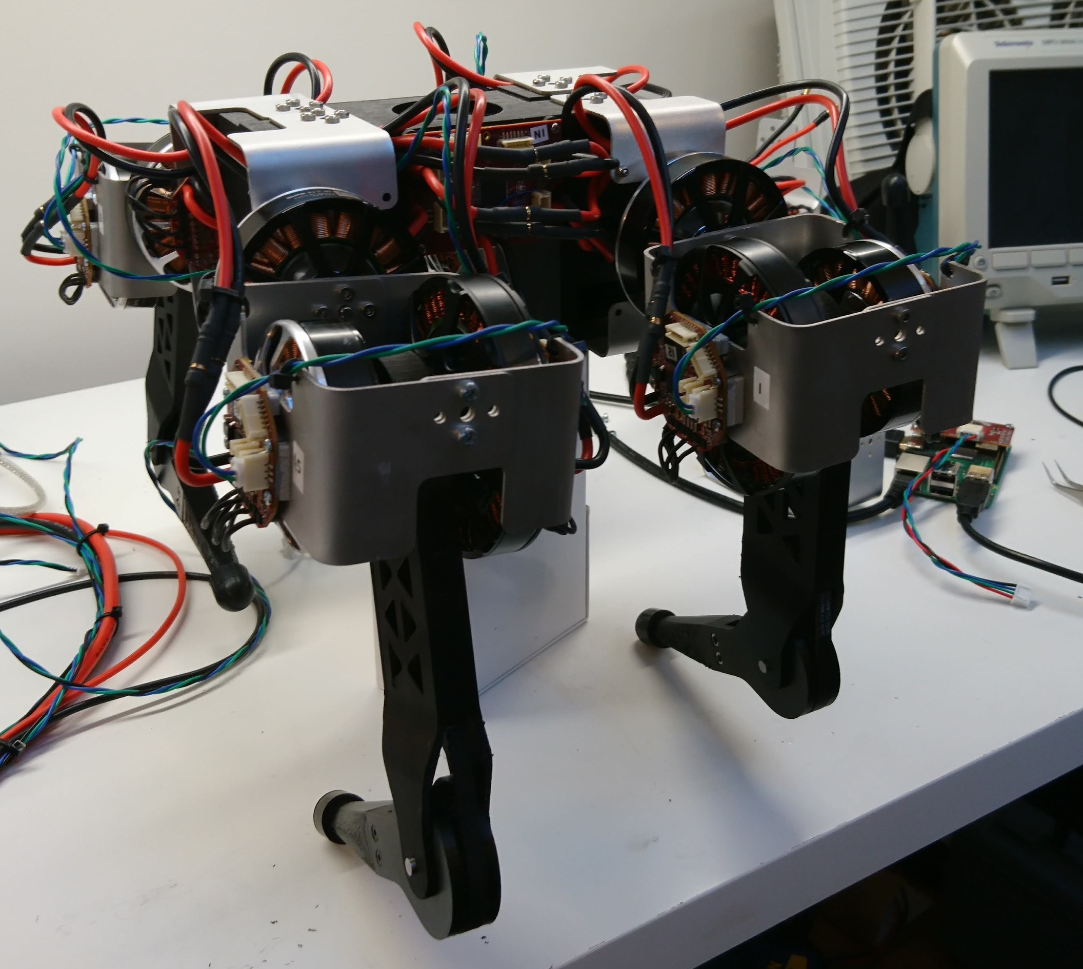
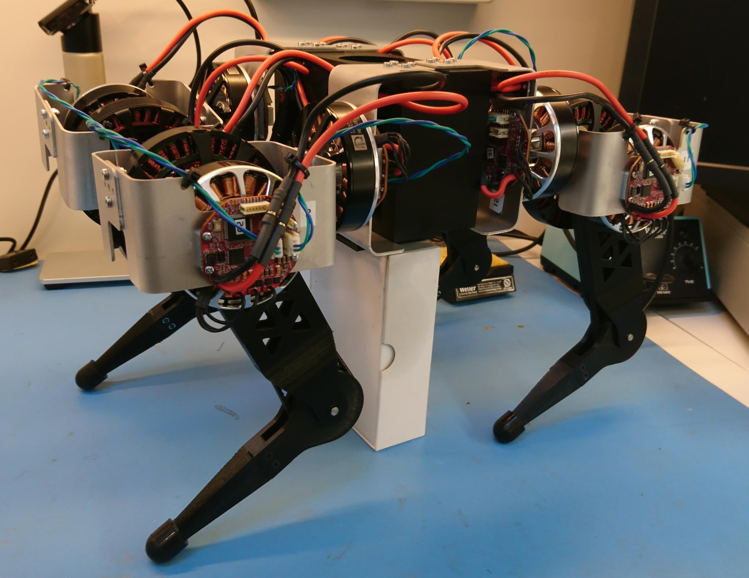
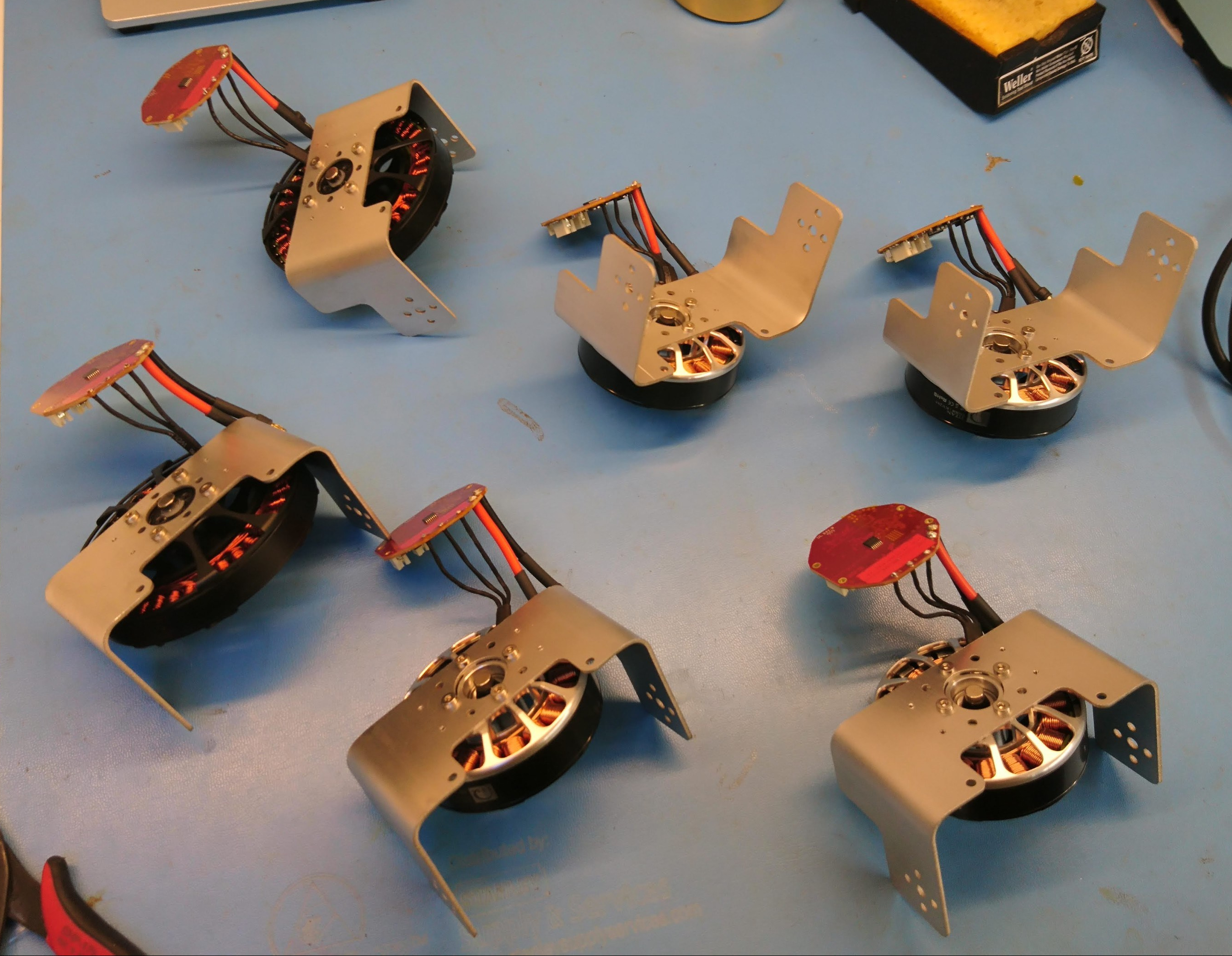
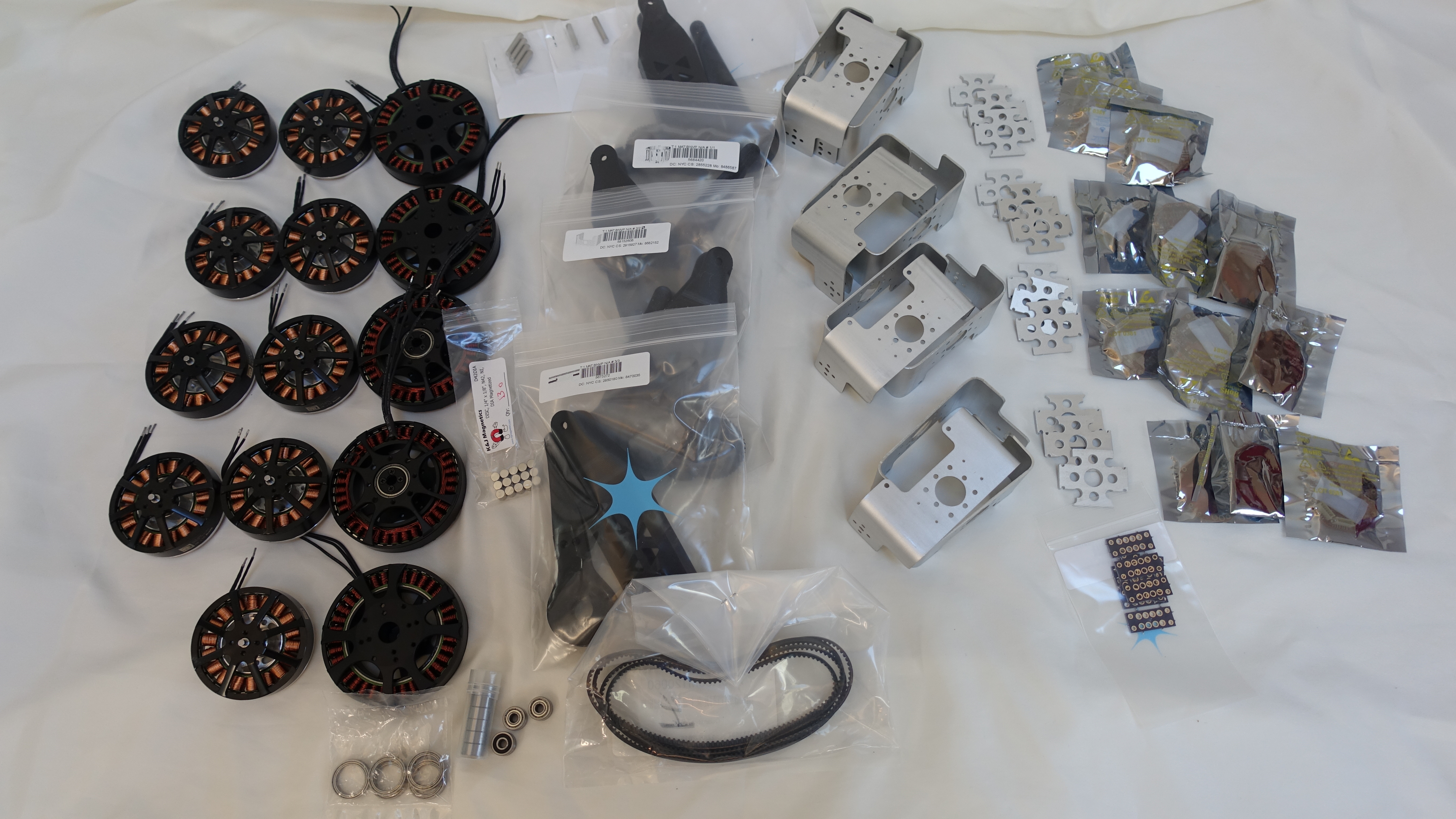
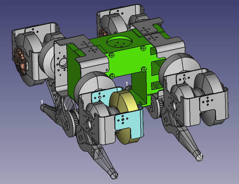
After getting the whole robot assembled, I quickly realized that changing the firmware on each of the 12 servos was going to be a big annoyance.  Doubly so, because the lateral servo programming ports were unreachable with this chassis design without disassembly.  Thus, I bumped up a deferred piece of work to implement a bootloader that would allow for reflashing the primary application over the RS485 communication bus.

Pre-bootloader state

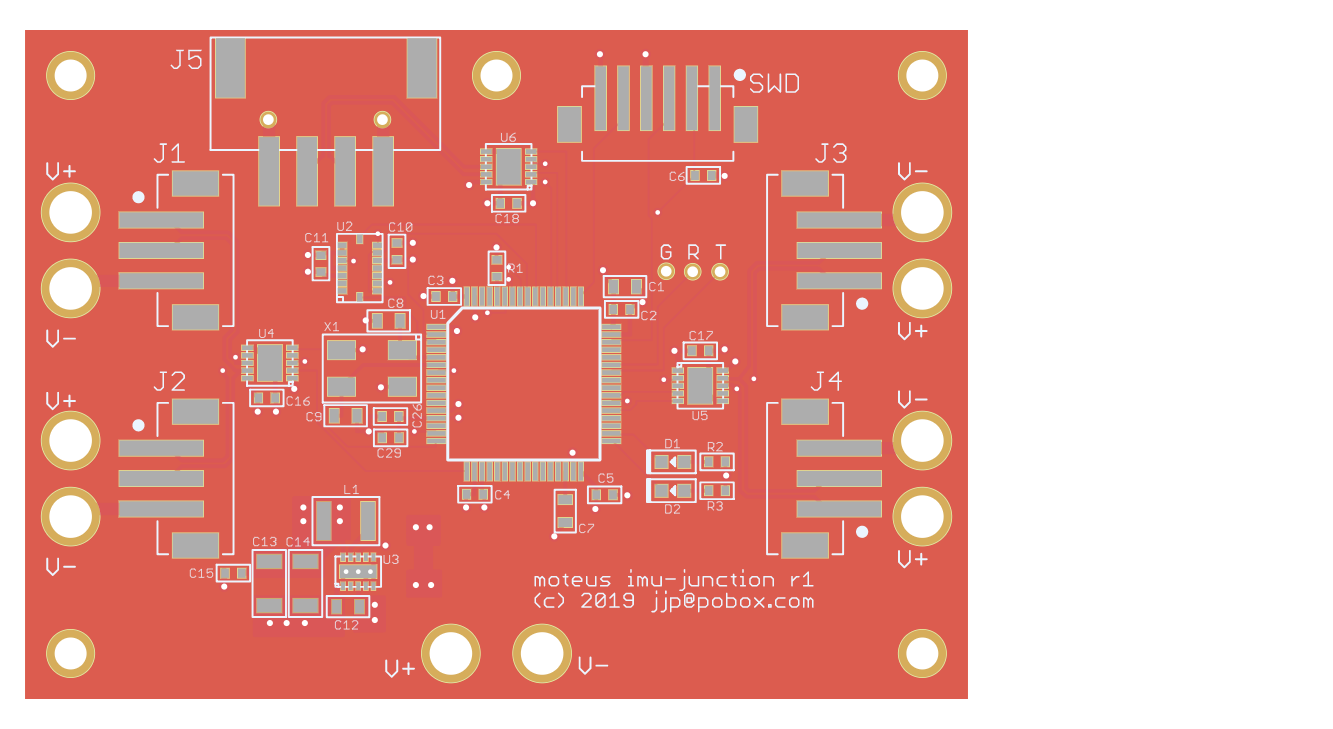
The moteus controller currently uses an STM32F446 controller, which has 512kb of flash memory.  The memory map pre-bootloader looked like:

First time powering all the motors!

After getting everything wired up and mechanically assembled, next was zeroing all the encoders and doing the first position control.  I discovered a number of problems that turned up by having a full 12 servos on the bus at the same time, which were resolved pretty easily, as well as many more pain points which I’ll need to address.

But, here is the pretty video (it ends when I push down enough to over-current my lab supply):

Populating r3.1 moteus controller boards

I am a big fan of MacroFab.  They’ve built a PCB + assembly + more service that is transparent, high quality, and nearly completely self service.  They appear to be making money, so hopefully they will stay in business for some time.

On top of that, they offer a “quick turn” option which gives you populated boards shipped 10 business days after you order them (and I’ve even had them ship out a few days early from time to time)!  The only annoyance is that the quick turn option is limited, as I’ve mentioned before, to boards that meet certain criteria, among them having 20 or fewer items on the bill of materials.  To try and get this first quadruped prototype up and running quickly, I’ve been exclusively relying on quick turn boards, which means making some compromises.  Even after some moderate design sacrifices, I haven’t been able to get the servo controller board to 20 parts.  At the moment it is 23.  Thus, when I received the first big-ish PCB order I’ve made (qty 28), I got to spend a morning populating the remaining 3 components on all 28 boards.

All parts received!

I’ve now managed to get all the custom and long lead time parts in house for the first version of a quadruped based on the new actuators I’ve been designing.

All The Parts!

All The Parts!

That includes all the motors, custom brackets, and at least moderately working versions of all the custom PCBs.  Now I just have to get the local rework done, get the software into a semi-reasonable state, and put it all together!

Quadruped chassis

Now that I have a semi-reliable actuator, I need to connect 4 of them together into a single quadruped robot.  Additionally, it needs to be able to mount a battery, the turret, and all the other miscellaneous pieces of a walking robot.

My draft design looks like this in CAD:

2019-03-05-205850_775x598_scrot

The four corners each are set to mount one leg to.  The central cavity will eventually house a battery compartment.  On the top is a mounting location for the turret, and the front has mounting studs for a power distribution PCB.  Each of the screw holes is designed to take a thermoplastic insert heat fit into place.

Quadruped Junction Board

The full quadruped robot needs to both distribute power from the primary battery and RS485 serial network to all 12 servos.  To make the wiring of that easier, I’ve made up a junction board to provide power connectors, distribute the data network, and act as the IMU for when that is necessary.

20190314-moteus-imu-junction-r1.png

The RS485 network is bridged between two halves of the robot.  One connection comes in from the controlling PC and two separate links go out, one for the left side and one for the right side.  This could eventually allow the controller on the junction board to take intelligent actions itself, such as querying the force applied on all 12 servos.  It could then return the result in a single RS485 transaction to the host computer.  I am expecting that will be necessary to achieve closed loop control approaching 1kHz.